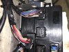
Recently bought a 2000 seadoo rx di....when I plugged everything into the mpem and replaced fuse in rear electrical box the mpem started smoking at plug 2 pin 25 and 26. The plastic on the mpem has started melting....the vts is unplugged aswell as 6 pin at stator. I have tried testing which fuse makes it smoke and seen no corrilation and sometimes blows 15A fuse in rear electrical box...might supposed to be a 30A. Leaning towards bad mpem as the plastic on the mpem is melted as you might be able to see in pics. Any advice would be helpful. Thanks


-
This site contains eBay affiliate links for which Sea-Doo Forum may be compensated.
You are using an out of date browser. It may not display this or other websites correctly.
You should upgrade or use an alternative browser.
You should upgrade or use an alternative browser.
2000 Seadoo rx di mpem smokes
- Thread starter Boyj1fox
- Start date
- Status
- Not open for further replies.
I used a heat gun on mine and removed it from the ski. Set it in the sun on a very warm day last week. I cleaned and resealed the box and the ski started right up... to my shock. It's not just the water but the impurities in the water that short circuit electronics.
Will try to set mine out but I feel it would still smoke even if I didn’t plug in connecter 2....if water is inside it should short circuit anywayI used a heat gun on mine and removed it from the ski. Set it in the sun on a very warm day last week. I cleaned and resealed the box and the ski started right up... to my shock. It's not just the water but the impurities in the water that short circuit electronics.
Sportster-2001-951C-Stock
Well-Known Member
I used a heat gun on mine and removed it from the ski. Set it in the sun on a very warm day last week. I cleaned and resealed the box and the ski started right up... to my shock. It's not just the water but the impurities in the water that short circuit electronics.
This is true, we used to make our own point-source water for this reason by combining ultra pure O2 and H2 to make steam. It wasn't cheap but we had to have this high purity to grow the semiconductor SiO2 insulators.
Find some 99% alcohol, it will soak that contaminated water right up. But where there's smoke, damage has occurred already.
My only worry is if I put another computer in it how can I assure it won’t Short out either? All I can do is hope?If it's smoking you'll likely be replacing it, unfortunately. Just need to make sure the culprit isn't outside the MPEM. Good Luck !!
Sportster-2001-951C-Stock
Well-Known Member
Sure, acetone would work as well to absorb water also a deep vacuum chamber to evaporate the water. MEK is hygroscopic was well. Depending on what you have of course, solvents can attack plastics for instance but not the epoxy case of an IC and most times not the silkscreen of an PCB.
MEK will remove your common rosin fluxes that can grow bacteria causing electrical signal shorts.
Alcohol is probably the safer solvent concerning plastics and from a health/safety hazard aspect.
The dial face paint of most gauges will suffer greatly from exposure to most solvents.
MEK will remove your common rosin fluxes that can grow bacteria causing electrical signal shorts.
Alcohol is probably the safer solvent concerning plastics and from a health/safety hazard aspect.
The dial face paint of most gauges will suffer greatly from exposure to most solvents.
Sportster-2001-951C-Stock
Well-Known Member
My only worry is if I put another computer in it how can I assure it won’t Short out either? All I can do is hope?
You'd better test your circuit best you can. Anything suspect gets plugged in last, after confirming all is well up to this point. NON-essentials get connected and tested last, for instance (yes, that's YOU, VTS!).
It's okay to use a small fuse, occasionally an incandescent bulb of reasonable current can be used as a fuse. For instance, say you're working on a 40W 110V power supply, you can use a 50W 120V bulb as a "fuse". If the bulb goes full bright, this is limiting the current which otherwise would be multiples higher. As the tungston element heats to a glow, it's resistance increases by a large amount.
I use 12V trailer test lights to locate shorts this way, pretty often. Two equal voltage and wattage bulbs in series will glow half as bright but if the circuit has a short, the single bulb glows full brightness.
.
Last edited:
Sportster-2001-951C-Stock
Well-Known Member
Have a look at this video:
Sportster-2001-951C-Stock
Well-Known Member
Oops, went for a swim with your smartphone?
There's a better solution than rice if you drop your phone in water
There's a better solution than rice if you drop your phone in water
So your saying plug in old mpem that smokes after disconnecting the battery and see if the light comes on? How would I test the mpem in specific for a short?Have a look at this video:
Sportster-2001-951C-Stock
Well-Known Member
Okay, see the battery positive terminal is disconnected from the battery? Then the test light is connected from the positive terminal of the battery to the positive battery cable.
(Let's assume he already confirmed his test light actually works, an unknown test light might not work but we'll ignore that possibility b/c it's easy to test the test light.)
As the test light is connected in the video, any current through the battery cable must pass through the test light. Worst case, the test light will limit the current to less than 1/3 Amp, this is 12.5V*0.333A =~ 4Watts in the case of a direct short (wiring malfunction). A sleeping computer should not consume much current (power) if the system is off, less than 20mA (0.020A), otherwise a larger drain will deplete the battery in hours, as the ski sits unused.
So lets connect our test light the same way he connected his, we should expect our light will glow either not at all or very dimly at most. If our bulb glows brightly, this means there's high current, possibly a direct short even, somewhere in the circuit that would draw much more current than we'd anticipate. Under the conditions we're attempting to create, the MPEM and it's attached components should not consume enough power to cause the bulb to glow brightly. If we pressed the start button under these conditions for instance, the bulb might glow brightly but that's about all that would happen.
So let's say this happens, our bulb glows brightly. For one thing, no smoke came from the MPEM b/c our bulb limited current to just 0.333A (4 Watts), nowhere near enough to cause thermal damage.
At the same time, we witnessed way more current than we anticipated, we were anticipating 0.020A or less, our bulb should not have been lit so brightly so now we know an unanticipated load, possibly a short, is present.
What should we do? We should begin disconnecting various connectors of the wiring harness to isolate the location of the short while watching our bulb, anticipating it should be dim, not fully bright.
Then, lets say when we disconnect the VTS connector, our bulb goes dim. There's our Ah-Ha moment, now we know the short has been eliminated because the current went to near zero, our bulb is no longer glowing brightly.
So we grab our electrical schematic diagram and possibly ohmmeter and begin to isolate the various components of the failed VTS. The other option might be to replace the VTS entirely.
So the bulb doesn't take place of our electrical schematic (An electrical schematic is an electrical road map of where current is traveling from positive terminal of battery, through the wires and various circuits then back to the negative terminal of the battery), it just limits the current to a low value that cannot thermally destroy things. That's handy b/c now we're not burning and smoking things while poking around in our investigation. We know well our jet ski electric starter motor will not crank the engine with such small current available, and the gauges are unlikely to operate, so we're not attempting to go for a ride or even start the engine, we're just testing to confirm there are no shorts. The bulb should not be glowing brightly or might glow dimly at most.
I'm not sure if I strayed off subject?
Last edited:
I think I understand....how would I figure out if the shirt is in the computer?Okay, see the battery positive terminal is disconnected from the battery? Then the test light is connected from the positive terminal of the battery to the positive battery cable.
(Let's assume he already confirmed his test light actually works, an unknown test light might not work but we'll ignore that possibility b/c it's easy to test the test light.)
As the test light is connected in the video, any current through the battery cable must pass through the test light. Worst case, the test light will limit the current to less than 1/3 Amp, this is 12.5V*0.333A =~ 4Watts in the case of a direct short (wiring malfunction). A sleeping computer should not consume much current (power) if the system is off, less than 20mA (0.020A), otherwise a larger drain will deplete the battery in hours, as the ski sits unused.
So lets connect our test light the same way he connected his, we should expect our light will glow either not at all or very dimly at most. If our bulb glows brightly, this means there's high current, possibly a direct short even, somewhere in the circuit that would draw much more current than we'd anticipate. Under the conditions we're attempting to create, the MPEM and it's attached components should not consume enough power to cause the bulb to glow brightly. If we pressed the start button under these conditions for instance, the bulb might glow brightly but that's about all that would happen.
So let's say this happens, our bulb glows brightly. For one thing, no smoke came from the MPEM b/c our bulb limited current to just 0.333A (4 Watts), nowhere near enough to cause thermal damage.
At the same time, we witnessed way more current than we anticipated, we were anticipating 0.020A or less, our bulb should not have been lit so brightly so now we know an unanticipated load, possibly a short, is present.
What should we do? We should begin disconnecting various connectors of the wiring harness to isolate the location of the short while watching our bulb, anticipating it should be dim, not fully bright.
Then, lets say when we disconnect the VTS connector, our bulb goes dim. There's our Ah-Ha moment, now we know the short has been eliminated because the current went to near zero, our bulb is no longer glowing brightly.
So we grab our electrical schematic diagram and possibly ohmmeter and begin to isolate the various components of the failed VTS. The other option might be to replace the VTS entirely.
So the bulb doesn't take place of our electrical schematic (An electrical schematic is an electrical road map of where current is traveling from positive terminal of battery, through the wires and various circuits then back to the negative terminal of the battery), it just limits the current to a low value that cannot thermally destroy things. That's handy b/c now we're not burning and smoking things while poking around in our investigation. We know well our jet ski electric starter motor will not crank the engine with such small current available, and the gauges are unlikely to operate, so we're not attempting to go for a ride or even start the engine, we're just testing to confirm there are no shorts. The bulb should not be glowing brightly or might glow dimly at most.
I'm not sure if I strayed off subject?
Sportster-2001-951C-Stock
Well-Known Member
Assuming the patient is your RX DI, Disconnect the 3 connectors on the computer one at a time while watching your test light. Let;s assume in the beginning, with all the connectors connected, the test light is illuminated brightly (indicative of a short somewhere).
There are 3 connectors on the MPEM, connector #3 contains the power from the battery for the MPEM, in pin25 of this connector. Disconnect this connector LAST, disconnect the other two connectors 1st. If immediately after disconnecting connectors #1 or #2, the test light goes dark or dim, the short is likely in the circuit of one of these connectors (#1 or #2). If the light goes dark or dim once you disconnect the last connector #3, this indicates the MPEM likely has a short.
This will tell us quite a bit more depending on when the light goes dark, so do this and we'll take it from there.
If the light goes dim when you disconnect connector #2, we need to electrically check the magneto and regulator. (Pin 25 and 26 of that connector are the voltage regulator pins.)
Connector #1 is the gauge pod interface, if disconnecting this connector causes the light to go dark, we should check that circuit.
Sportster-2001-951C-Stock
Well-Known Member
Man I'm learning some shiznit !!I've never used a light to determine current flow. That's cool !!
This is a VERY important feature of incandescent lamps, their resistance is low when the filament is cool but as current passes through, the filament heats up and resistance become high, limiting current to a predetermined level.
Ok so I hooked up a test light this morning and I saw no difference in the light until I unplugged the connector #3 or power in plug...is it safe to say the mpem is shortedThis is a VERY important feature of incandescent lamps, their resistance is low when the filament is cool but as current passes through, the filament heats up and resistance become high, limiting current to a predetermined level.
Sportster-2001-951C-Stock
Well-Known Member
Ok so I hooked up a test light this morning and I saw no difference in the light until I unplugged the connector #3 or power in plug...is it safe to say the mpem is shorted
Sounds that way but leaving #1 and #2 disconnected, let's pull the MPEM fuses one at a time and see if the test light goes out or dims? This might help us isolate which section of the MPEM is causing the light to glow brightly.
Sportster-2001-951C-Stock
Well-Known Member
Moving forward from there, and assuming your MPEM is damaged, we need to investigate possibilities for why it was damaged before just installing a new MPEM.
We might also need to discuss using a slightly larger bulb, such as an 1157 but we'll see.
We might also need to discuss using a slightly larger bulb, such as an 1157 but we'll see.
Previous owner said his son plugged in a 6 pin connecter near the battery which goes to vts...and he said it needs a new mpem and a new rectifier.Moving forward from there, and assuming your MPEM is damaged, we need to investigate possibilities for why it was damaged before just installing a new MPEM.
We might also need to discuss using a slightly larger bulb, such as an 1157 but we'll see.
Sportster-2001-951C-Stock
Well-Known Member
It;s beginning to look that way, he may be correct.
I see the VTS is also part of the connector #3, is the VTS module currently disconnected? If not, then disconnect it with #3 connector connected to the MPEM and see if the light dims.
I see the VTS is also part of the connector #3, is the VTS module currently disconnected? If not, then disconnect it with #3 connector connected to the MPEM and see if the light dims.
Last edited:
Both the 6 pin and the 2 pin from the vts was disconnected when testing aswell at the stator 6 pin in front of motor.It;s beginning to look that way, he may be correct.
I see the VTS is also part of the connector #3, is the VTS module currently disconnected? If not, then disconnect it with #3 connector connected to the MPEM and see if the light dims.
- Status
- Not open for further replies.
Similar threads
- Replies
- 2
- Views
- 351
- Locked
- Replies
- 279
- Views
- 14,569