


-
This site contains eBay affiliate links for which Sea-Doo Forum may be compensated.
You are using an out of date browser. It may not display this or other websites correctly.
You should upgrade or use an alternative browser.
You should upgrade or use an alternative browser.
Wont run
- Thread starter justinb
- Start date
- Status
- Not open for further replies.
justinb
Active Member
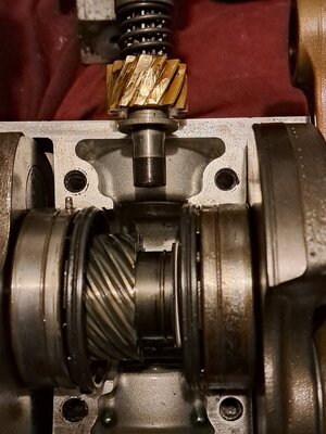
Hi Mikidymac, see attached picture you can see the brass sprocket teeth is worn , this was part of the damage from the rotary valvePer page 04-07-02 of the service manual 0.30mm +/- 0.05mm
My concern in the steel sprocket inside the crank has somehow moved towards the side not dead centre anymore.
It's not damaged either , how can I move it back to the middle without putting it in a press?
All the bearings are fine so I don't want to break the crank down unless I need to , to move that centre sprocket, do u know the name or part no I can't seem to find it
Thanks
Attachments
justinb
Active Member
Was thinking a blow tourch to heat it up then try knock it down with a screw driver , concerned about the seal next to it getting damagedIt definitely has moved.
I am not sure the best way to get it centered again but our resident machinist @etemplet might have some ideas.
Wanted to ask best way to clean / soak the crank shaft without damaging existing bearing etc
Thanks
justinb
Active Member
I will stick it in a container with a lid over it how long can I soak it forI might clean the cranks in gasoline in a well ventilated area with no sparks. I am not suggesting it though as it can be extremely dangerous.
I haven't tried to reposition a crank gear yet but chances are if it moved once it will move again. If I only wanted to move it over without damaging it I'd try a hose clamp tightened around the Diameter and gently pry on the clamp or try using 2 clamps separated as much as possible. Any force applied directly to the gear will likely damage it and no heat can be applied. Need to solve the problem with the gear losing it's location. What caused the brass gear to wear? Was it that the gear on the shaft moved? Whatever you do... very gently. I have a crank open in the shop I'll take a look at it tomorrow. Something has to locate the gear and lock it into position. 6500RPM.... it's just gonna move away from thrust if it isn't secure.
justinb
Active Member
HiI haven't tried to reposition a crank gear yet but chances are if it moved once it will move again. If I only wanted to move it over without damaging it I'd try a hose clamp tightened around the Diameter and gently pry on the clamp or try using 2 clamps separated as much as possible. Any force applied directly to the gear will likely damage it and no heat can be applied. Need to solve the problem with the gear losing it's location. What caused the brass gear to wear? Was it that the gear on the shaft moved? Whatever you do... very gently. I have a crank open in the shop I'll take a look at it tomorrow. Something has to locate the gear and lock it into position. 6500RPM.... it's just gonna move away from thrust if it isn't secure.
Thanks I will try what u have said , we are uncertain what has happened we found the rotary valve was bent and a piece broken off how it happened we don't know .
Assuming this piece or what ever fell into the chamber went into the crank case , destroyed the brass sproket and in the process caused the steel sprocket to move over
Only found fine pieces of steel in the bottom
justinb
Active Member
Hey mikidymacPer page 04-07-02 of the service manual 0.30mm +/- 0.05mm
Can you please help me on this statement , I have found an engineering place that can machine the rotary valve cover and block
So reading the manual and what u have said , my understanding is with the cover on the block all bolts torque to 20nm
The space between these 2 parts should be the value thickness of the rotary valve and free space off 0.30mm?
To achieve this I need to ensure the face of the valve cover is flat and true dimension all round and ensuring where the o ring sits it has that grove of 1.00mm
So with saying that if I have damages on the main block surface of , as an example of 0.35mm , I will need to take that amount off the valve cover keeping in mind I need to add all these values together and cut in such away that once rotary valve in installed and cover is on we still have the 0.30mm clearance
Am I understanding this correct
Thank you
How much are they going to charge you for that? Before I machined the engine casing and buy a good used engine casing. Take some pictures of the parts and post them. I machine my own rotary valve covers. It's fun thing for me. ") For somone that doesn't have access to machines and has to pay for that kinda work I wonder the price difference in comparision to a good used cover. Remember too that the people doing the machine work don't always get it right.
For somone that doesn't have access to machines and has to pay for that kinda work I wonder the price difference in comparision to a good used cover. Remember too that the people doing the machine work don't always get it right.
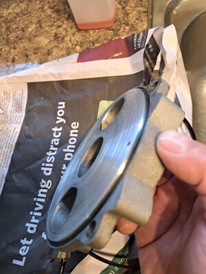
The assembled measurement, since I don't do millimeters , is (.010" - .014") I use a piece of (.032") solder to check the clearance. I have taken measurements of (.017") and had no issues with engine starting and I think you can get away with more than that. Most of these covers are worn even though the readings are not all that bad. Here is a picture of a cover I did while back in the lathe. The job is kinda tedious but that's what we do. You learn a lot about how these things wear when you are machining them. This cover was worn pretty bad.

For somone that doesn't have access to machines and has to pay for that kinda work I wonder the price difference in comparision to a good used cover. Remember too that the people doing the machine work don't always get it right. The assembled measurement, since I don't do millimeters
, is (.010" - .014") I use a piece of (.032") solder to check the clearance. I have taken measurements of (.017") and had no issues with engine starting and I think you can get away with more than that. Most of these covers are worn even though the readings are not all that bad. Here is a picture of a cover I did while back in the lathe. The job is kinda tedious but that's what we do. You learn a lot about how these things wear when you are machining them. This cover was worn pretty bad.justinb
Active Member
HiHow much are they going to charge you for that? Before I machined the engine casing and buy a good used engine casing. Take some pictures of the parts and post them. I machine my own rotary valve covers. It's fun thing for me.
The assembled measurement, since I don't do millimeters
View attachment 62658
Don't give me ideas .... might send it to you to fix lol, the guy said it will cost me about 500 NZ dollars
The issue I have here getting 2nd hand parts is impossible not a big market here.
I see refurbished motors that side is cheap problem is getting it here import and freight costs will make it too expensive.
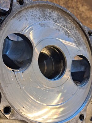
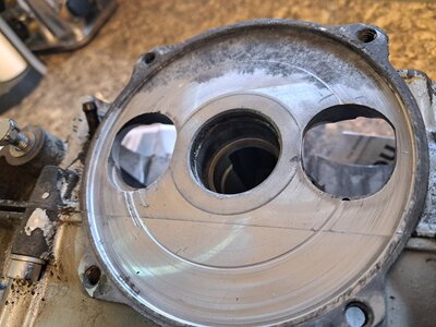
See attached pictures I don't think much work needs doing on the cover it's the block part that has the bad scratches
So as u stating with the 2 pieces together I need to ensure with the rotary valve in between it I must still have 0.10" -0.14" clearance?
Or is this valve without the rotary valve in
Thank you
justinb
Active Member
Hi
Don't give me ideas .... might send it to you to fix lol, the guy said it will cost me about 500 NZ dollars
The issue I have here getting 2nd hand parts is impossible not a big market here.
I see refurbished motors that side is cheap problem is getting it here import and freight costs will make it too expensive.
See attached pictures I don't think much work needs doing on the cover it's the block part that has the bad scratches
So as u stating with the 2 pieces together I need to ensure with the rotary valve in between it I must still have 0.10" -0.14" clearance?
Or is this valve without the rotary valve in
Thank you
Attachments

- Status
- Not open for further replies.
Similar threads
- Replies
- 2
- Views
- 127