Stators out metals in

Note: This site contains eBay affiliate links for which SeaDooForum.com may be compensated
Status
Not open for further replies.

skenor

New Member
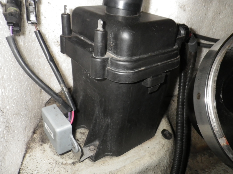
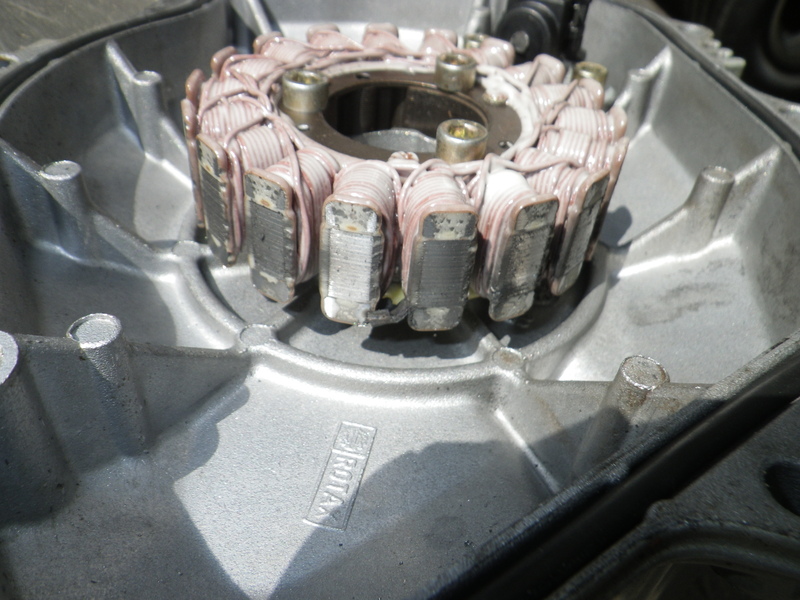
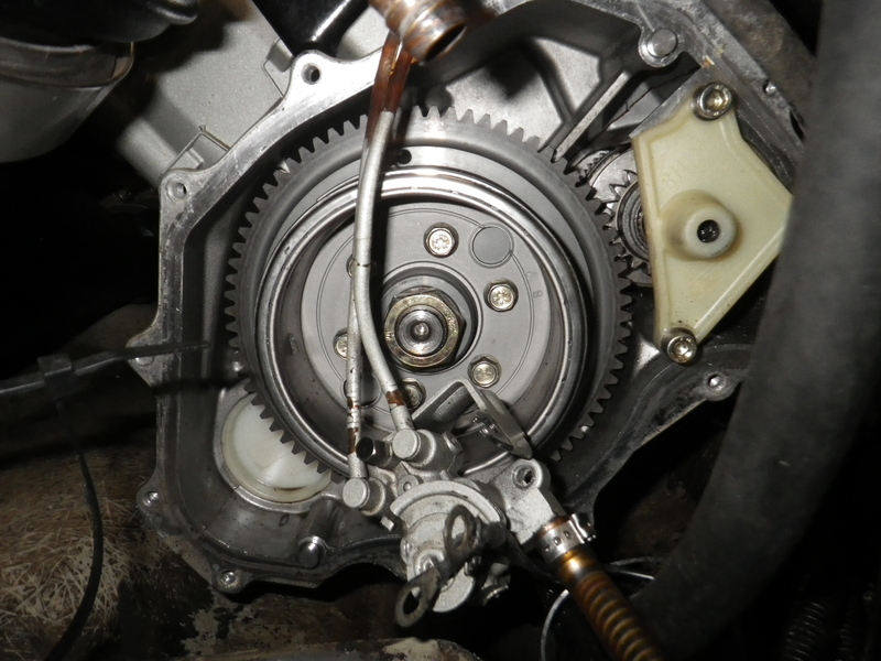
Hey hi, was having probs with blowing my 15 amp fuses, Stator is out and found a piece of metal wedged in there. I would just like to know if anyone knows where it may have broke off from, it isn't shavings. I cant get my head to have a good look around in there don't really want to start blowing air inside there. Also Should I be good to go after cleaning it up a bit, looks to be pretty clean. Thx please
151.jpg

152.jpg
 
oh I didn't see that thing it fell off into the pit. I probably woulda missed it .Thx dude. Have you got a sec to tell a guy how to test it exactly, or where to find info. I don't have any adapters either im not the best with that stuff. Thx again.
 
I see some piece of metal sticking to the magnet inside the flywheel. Any metal bits will damage the stator winding as the wheel turns. Maybe also, the regulator/rectifier will be damaged also.

I cant see it closely but maybe a piece of gear tooth?

You can use an ohmeter or a test light to test stator, which one do you have? Here is the electrical diagram of the stator and test light connection, it's essentially three copper windings connected together to make a 3-phase Wye alternating current generator. The test light uses battery voltage.

An Ohmmeter will reveal more detail than a test light but we're looking for a shorted winding to case ground and a test light will reveal this.

Very clean ski! :)
 

Attachments

  • Wye 3-phase winding seadoo 951.jpg
    Wye 3-phase winding seadoo 951.jpg
    67 KB · Views: 35
You are exaCtLY RIGTHT BUD. There was half a gear tooth in there as well. Must be the starter, bendix looks ok Ive got the test light and ohm meter I will check it out. The rectifier that's the one mounted next to front elec.box?
 
The rectifier on the 951 motor is normally built into the MPEM but this is an early model so not for sure. The three yellow stator wires are always connected to provide AC current from the stator generator winding to the rectifier.

An Ohmmeter should measure open circuit to case ground of all three yellow wires to the case. Also the ohmmeter should measure ~ 1 Ohm between any two of the three yellow wires of the stator winding, check all three each should be 1 Ohm. Ohmmeter set on lowest scale of resistance, maybe your meter's lowest scale is 200 Ohm scale.
 
Here's the electrical schematic diagram of the 2001 model 951 jet ski, I think yours is VERY similar but maybe some small differences? The BRP shop service manuals are posted online, check seadoomanuals dot com. Maybe not '98 model, but check b/c you will rejoice when you discover the TONS of valuable information. Even details of stator resistance checks are included.
 

Attachments

  • 2001 seadoo 951 schematic diagram.jpg
    2001 seadoo 951 schematic diagram.jpg
    147.7 KB · Views: 21
Rectifier?
155.jpg

I get a reading of 1 ohm like said and nothing when checking through the core. Its going back together now for a start. Im sure with the chipped tooth tho i'll be looking to fix something else soon too. its not that bad.
 
That sucks they aren t cheap, if I have to do an external one and mabey I should, I'm gonna need the step by step buuuuuud.
 
Step by step:
1) Remove three yellow wires from MPEM connector #2 and connect them to ext reg. yellow wires in any order, doesn't matter.
2) Connect red regulated DC output wire of regulator through a 15A fuse to battery positive terminal.
3) Connect case ground, or black wire of regulator to engine ground or battery negative terminal.

Make sure the 3-phase regulator you choose can handle the current, the RFI, 951-DI or 4-tec regulator are heavy duty enough.

Fire up confirm about 13.8V at battery, less than 14.4 and more than 13.5V is okay.
 
Will the regulator draw any current while at-rest or is it only energized when the stator is supplying the 3-phase AC voltage? In other words, it wont drain the battery? The custom harness is $70 but sounds like it is only necessary to make it more OEM quality.
 
Will the regulator draw any current while at-rest or is it only energized when the stator is supplying the 3-phase AC voltage? In other words, it wont drain the battery? The custom harness is $70 but sounds like it is only necessary to make it more OEM quality.

The regulator should not draw current while the engine is off. (except for a very tiny amount that is negligible for months).

The harness is a work of beauty, only b/c it's plug and play. :)

Here are two diagrams suggesting how to check the rectifier diodes and scr's by using a test light, you're the test bed guinea pig. :)
 

Attachments

  • 3-phase scr test.jpg
    3-phase scr test.jpg
    135.8 KB · Views: 20
  • 3-phase diode test.jpg
    3-phase diode test.jpg
    136.3 KB · Views: 15
Last edited by a moderator:
Status
Not open for further replies.
Back
Top