


DooWacka
Active Member
Here is the entire document in pdf form: View attachment Seadoo DI Fuel Pump Replacement Guide .pdf
Seadoo DI (Direct Injection) Fuel Pump Replacement Guide
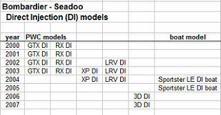
BackgroundThe Bombardier Seadoos with Direct Injection (DI) are amazing machines, having both performance and economy, but they have had issues with fuel pumps. The Airtex E1067 fuel pump contracted by Bombardier is a specialized high pressure unit that needs only about 4 or 5 amps of current to provide the required 107 psi fuel pressure. However, the metal roller-vane design does not do well with particulates or water in the fuel, which often causes premature pump failure. Most likely due to these issues, Airtex no longer makes this pump, and even if they did, couldn’t sell it to anyone except Bombardier. When faced with a failing fuel pump, DI owners must either replace the entire fuel pump module assembly with an OEM Bombardier part (approx. $800-$1000), or rebuild the module with a suitable fuel pump. There are 15 Seadoo PWC and 2 boats that have or will face that dilemma, as shown in this table.
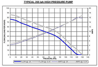
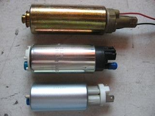
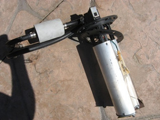
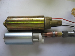
There are many in-tank (submersible) automotive fuel pumps available, but few that can achieve the required 107 psi pressure needed for Direct Injection. The few candidate pumps that have been “discovered” are mostly referred to as “255 lph” (liters per hour) pumps and built competitively to the well known Walbro GSS-342 (340 series). Typical pump performance curves are shown here for reference. These curves are for the “High Pressure” version of the “255 lph” pumps. The flow curves show that a 255 lph (67 gph) flow rate is at the common 40 psi used in many automotive applications, whereas at 107 psi the pump can still deliver about 15 gph. That is enough flow to feed the 951 DI motor when demanding its highest performance usage. The electrical power curves shown in the graph indicate these pumps on average require about 14A (amps) of current to maintain the 107 psi pressure. Typically these types of pumps can be found that require “only” 12A for the 107 psi. The picture shown here compares three pumps, from top to bottom, the Seadoo OEM Airtex E1067 roller-vane, Walbro GSS342 gerotor (or HFP-342 composite vane-impeller), and the HFP-342DI (HFP-RTN) composite vane-impeller pump.
Since the maximum output of the magneto power system in the 951 motor is about 18A, even a 12A power draw is “marginal” when considering the rest of the power requirements of the PWC, and that the battery must also be re-charged while riding.
The easiest and best fuel pump replacement should fit into the OE fuel pump module assembly, with the least modifications, and still keep all the original module design functions. The key designs of the module include a fuel intake on the very bottom of the tank, a spring to keep the intake on the bottom yet allow tank flex and easy installation, a reservoir to contain the return flow from the fuel rail, and a foot valve to keep the reservoir from leaking back into the tank. Some early methods of installing these replacement pumps would lose all of this functionality by hose clamping the pump inside the module, using a single filter sock attached to the pump, and use of an outlet hose eliminating the spring feature. This mounting has several drawbacks including the pump intake is no longer on the tank bottom, but about 2” above the bottom, diminishing the range of a ride. The reservoir functionality is also gone. To keep module functionality, and minimize modifications, a pump is chosen with an inlet port the same size as the OE pump port, so it exactly fits into the “inner” (second) filter screen, and aligned inlet and outlet ports to allow the same OE type of axial pump mounting. The 342 model of the “340” pump series has these features, whereas the 340 has too large of intake, and the 341 inlet and outlet ports are misaligned.
Current Best Replacement Pump
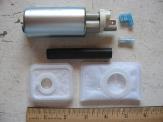
The current best Seadoo DI replacement fuel pump is the HFP-342DI from “High Flow Performance” which supplies 107 psi yet draws only 9A compared to the more common 12A plus power requirement of other similar pumps. The kit from HFP (HighFlowFuel.com) also includes the two filter strainers (FS220 and FS242) to exactly replace the OEM fuel module filters, two fuel resistant electrical connectors, and a piece of high pressure fuel resistant hose with hose clamps. The desired hose, a short black hose, or a longer flexible white hose, can be specified when ordering the pump.
Fuel Pump Module Removal
The following fuel pump replacement guide uses a 2001 GTX DI, but is similar to other DI Seadoo PWC and boats.
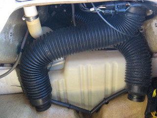
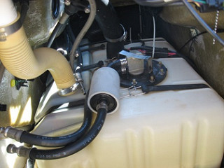
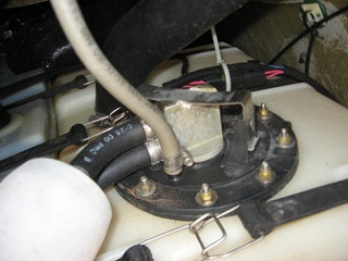
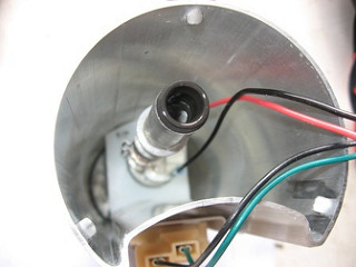
The easiest module access is obtained by removing the front storage compartment, then strap the hood open so it doesn’t fall on you. It is also easier if you remove the “glove box” console storage compartment to additionally provide top access. Remove the front air supply tube, and also the second one you can see behind it. The first tube can probably just be pulled off the upper connection, if not just loosen the large ratcheting strap. Only the “zip tie” (cable tie) that holds the top of the second tube to the hull needs to be clipped, the others can simply be left intact and slipped off the tube ends. Leave the zip ties that hold the tubes in their “Z” shape. Remove the filler end of the fuel fill hose from the hull and contort it out of the way behind the steering “column”. The first picture shows the view after the storage compartment is removed, and the next one shows the top of the tank and module after the air-tubes are removed and the fuel fill hose is tucked out of the way.
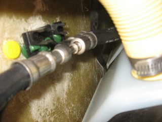
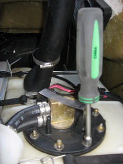
Unclick the fuel lines from the starboard hull supports, and use a 5/16” QC tool (a red metal tool shown) to separate the “Quick-Connects” for both the fuel supply and return lines.
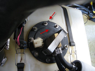
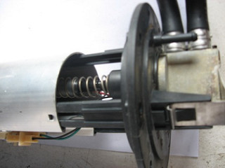
Remove the gray vent hose from the top of the now visible module, and unclip the electrical connector. Use an 8mm nut driver to remove all the nuts holding the module to the top of the tank. Save the nuts and washers aside in a container so they don’t get lost in the bilge, since the nuts are brass and the washers are stainless steel, a retractor magnet won’t help to retrieve them. In the view from the top, notice the alignment arrow on the fuel module top, pointing at both the PWC port side, and the rubber gasket protruding tab (red arrows). Due to the uneven spacing of the mounting studs, the gasket and module can only go back in properly, with these aligned.
Carefully lift out the fuel pump module, noting there is a float for the fuel sensor (gauge) on the end of a pivoting metal rod. It helps to rotate the module 180 degrees when half way out so the bent float rod has a better exit angle. If it helps, remove the rod from the gauge now instead of later, with careful prying at the attachment point to pop it out of the plastic retainer clip on the gauge. The module reservoir will be partly full of fuel that can be poured into a container while tipping the module out of the tank or, if small enough in volume, can be poured out after module removal. Whatever fuel is spilled from the module or the fuel line disconnects will evaporate quickly if the hull is left open and well ventilated. After the module is removed, cover the tank opening to cut down on fuel evaporation and contamination.
Module Disassembly
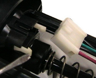
Unplug the electrical connector from the fuel gauge and remove the float to avoid damaging the gauge. Unplug the electrical connector from the underside of the module top. The bottom filter screen can easily be removed from the module bottom at any time. Unclip the three sliding clips that hold the aluminum reservoir, and separate it from the top with hoses and external fuel filter can. The plastic outlet tube will extract from the “sliding seal” and the spring will come loose. The fuel pump can be pulled out of the reservoir now, if desired. You CAN do all the work through the top opening of the module reservoir, OR drill out the two aluminum pop rivets and remove the bottom of the reservoir making things easier on re-assembly. Two metal screws or new pop rivets can be used to anchor the bottom later. If the inner filter screen & rubber grommet has a good grip on the pump inlet, it will come out still attached to the pump, otherwise it will remain attached to the module bottom. Remove the inner filter from the module bottom keeping track of the underlying foot-valve components, which consists of a metal washer and a thin rubber washer. Separate the black rubber grommet from the inner filter since you will re-use this on the new filter screen.
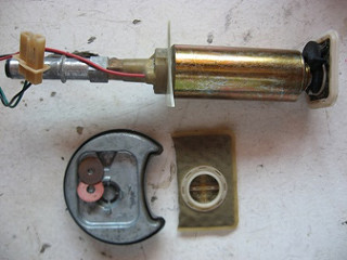
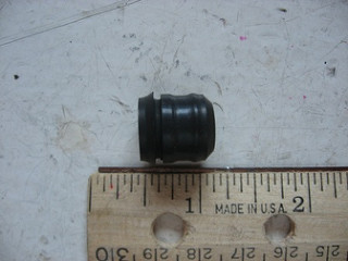
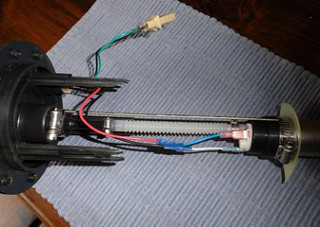
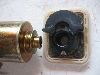
Shown here is the OE fuel pump with the attached seal carrier, both inner and outer filter screens, and the module bottom with foot-valve washers. The next picture is of the removed sliding-seal.
Fuel Pump
Clip the old pump wiring off close to the pump to leave as much wire on the harness as possible. Slip the thin white plastic sheet off the pump body which supports the pump in the middle of the module. Unscrew the aluminum sliding-seal carrier from the top of the OE pump. Check the flexibility and viability of the black rubber sliding-seal. If it is still in good shape then the sliding seal and spring system can be retained. On RARE occasions this seal can fail causing loss of pressure even when the pump is still good. If the seal has failed, there is no known replacement, so a hose must be used between the top of the pump and the output tube where the seal used to slide. Then the spring system must be abandoned and other methods used to support the pump and hold the module together and firmly on the tank bottom. For example, see the novel flex-hose solution of “baddb1”: http://www.seadooforum.com/showthread.php?54790-2002-GTX-DI-Fuel-pumps
A picture from the forum thread showing the flex hose install is shown for reference.
However, we won’t discuss those solutions any further here, refer to the post on the forum.
The OE fuel pump was rigidly screwed to the sliding seal carrier, so with the pump bottom also held firmly by the inner filter grommet, the thin white plastic pump support could easily hold the pump in the middle of the module. This is no longer the case when the rigid connection is replaced with a flexible piece of hose, so a hose reinforcing method is needed to stiffen the connection. Rigidity from the pump inlet all the way through to the sliding seal is required so that there is no “tilting” of the seal interface which would cause leakage and pressure loss. This “tilting” and pressure loss has been observed on less rigid installs, due to the high g-forces associated with high speed PWC riding, maneuvering, and wave jumping or wave “crashing”.
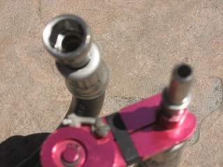
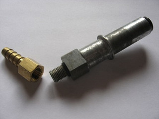
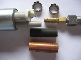
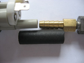
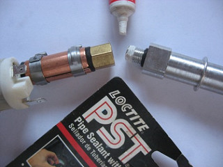
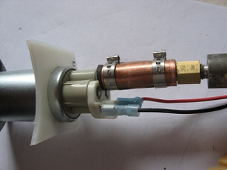
The best solution found is to split a ½” piece of copper pipe lengthwise and anchor both halves around the hose with the same hose clamps used to hold the hose to the pump and seal carrier. To make the hose attachment to the seal carrier rigid, use a 5/16” brass hose barb with a female 1/8” NPT. These pictures show the OE pump inlet and rubber grommet, and the brass barb fitting with the seal carrier.
The 1/8” FNPT (FPT) doesn’t screw on all the way to the SAE 3/8-24 seal carrier thread since the barb is a tapered pipe thread, in addition to having 27 threads/inch rather than 24. However, it screws on pretty far and makes a rigid connection. The taper makes a good seal, especially with some Loctite PST 592 Teflon pipe thread sealant (same as used on the jet-pump oil filler plug). If the FPT is re-tapped to a 24 thread, the barb screws on farther but does not seal as well without the OE O-ring (and O-ring pocket). Therefore this is not recommended unless you have the ability to mill the O-ring pocket into the barb FNPT end. Some have tried not using a barb fitting and just placing the hose over the seal carrier thread. This apparently has worked for a time, but is not the first recommendation since it may not seal as well long-term, and the length of thread inside the hose is so short, it is not a rigid connection at all by comparison.
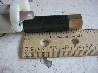
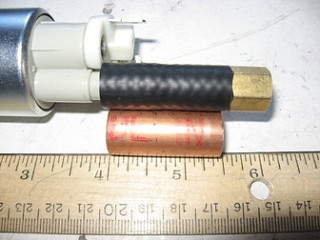
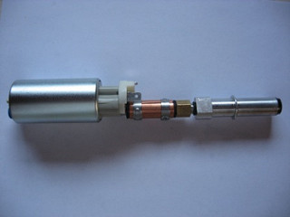
Measure the length needed of special in-tank black high pressure fuel hose (SAE J30R10 specs) to connect the pump outlet and brass barb fitting. Inferior rated hose will turn to mush after long immersion in fuel. Allowing for the barb and pump outlet lengths, a piece of hose about 1¾” long is appropriate, remembering that the hose length lessens about ¼” when stretched (swelled) over the pump outlet and barb fitting. Cut the copper pipe for the stiffener only a little less than the installed hose length to avoid interference with either the pump or the barb’s female end.
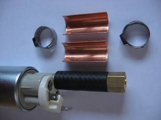
Install the hose on the pump and the barb fitting on the other end, then clamp the copper stiffener “shells” over the hose with either Oetiker clamps (17mm), or high quality all stainless worm drive hose clamps. With the copper to “smooth” out the pressure, a standard worm-drive hose clamp would be sufficient since the “flat spot” usually associated with the worm gear is smoothed out by the copper. Then screw the seal carrier into the female barb fitting using a bit of Loctite PST 592, or some other equivalent paste, on the threads as a sealer. Don’t use white Teflon tape since it will dissolve in fuel. Don’t tighten too much, or the threads will strip since they are different size.
Last edited by a moderator:


") When I ordered one they not only didn't do that but they forgot to include the black tubing I
When I ordered one they not only didn't do that but they forgot to include the black tubing I
