SeaDoo Speedometer sensor fix instructions

Note: This site contains eBay affiliate links for which SeaDooForum.com may be compensated

69DartGT

Member
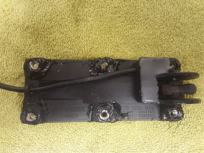
Hello, I thought I would post how I fixed the speedometer sensor for our 96 GTX's. This is for the 2 wire sensor with temperature sensor.

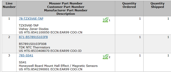
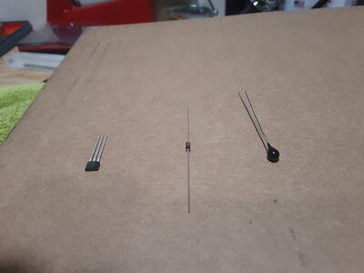
These are the components I replaced and their part numbers.
20240107_162641.jpg
Screenshot 2024-01-10 163632.png
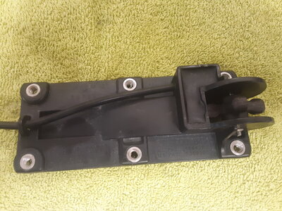
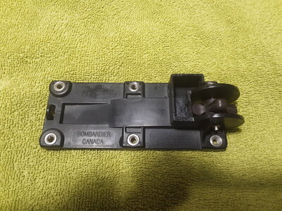
This is the sensor.

20240107_152640.jpg
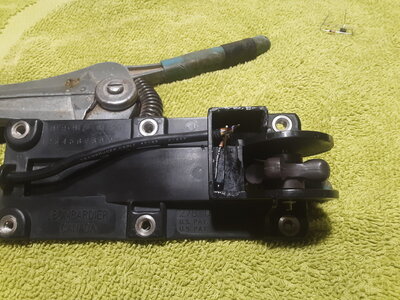
First thing I did was to cut the wire flush with the case.
20240107_152824.jpg
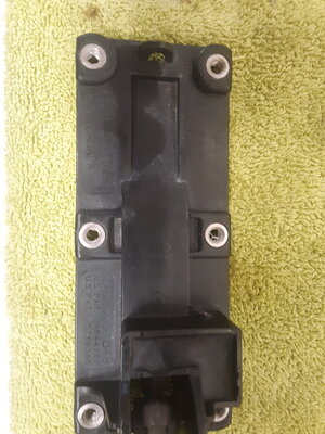
Then I drilled a series of holes into the potting. There is no use in trying to save any of the old components because I replaced all of them.
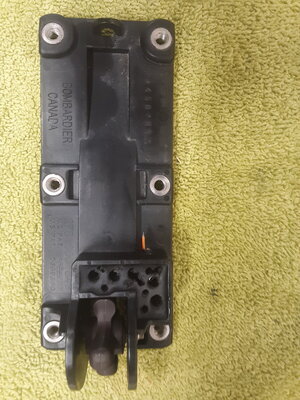
20240107_153531.jpg
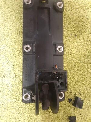
Now I used a sharp little chisel to scrape out all of the potting.
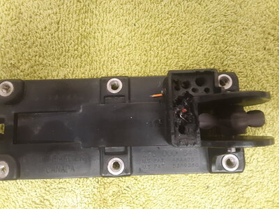
20240107_153757.jpg20240107_154041.jpg20240107_161637.jpg
After all the potting is removed, reinsert the wire with the ends stripped.
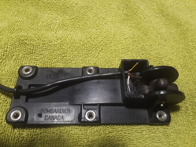
20240107_162247.jpg
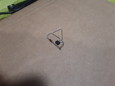
Now I soldered the diode to the right leg of the SS41. The side that has the printing and the 2 angles on the SS41 has to face the paddle wheel or it will not work.
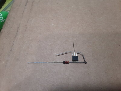
20240107_163600.jpg
 
Last edited:
20240107_163906.jpg

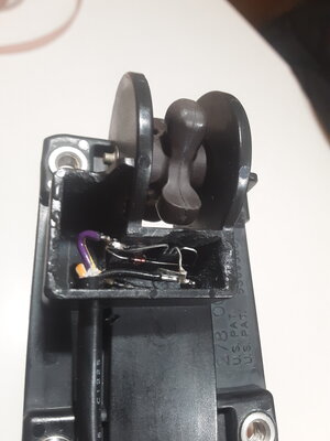
Next I put the thermister in the empty case. One leg is soldered to the TA-OR wire and the other was turned up to be connected to the middle leg of the SS41 and the BK-OR wire.20240107_165023.jpg
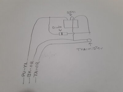
Then you install the SS41 and diode into the cavity. The second leg of the thermister, the middle leg of the SS41 and the BK-OR wire are soldered together and the Left leg of the SS41 the leg of the diode and the PU-YL wire are soldered together.

20240107_171629.jpg
Here is a simple diagram of it.

20240110_165126.jpg
After you have this done, test it on the ski to make sure it works and then repot it. I used a 2 part auto seam sealer for the potting.

20240107_152727.jpg
I have about $16 in parts and I fixed 2 sensors. Now both the digital and analog speedometers work on our 96 GTX's. Hope this helps anyone looking to do this fix. If you have any questions just ask. Scott.
 
Last edited:
Questions, the hall effect sensor, does it have to be within a certain range of the wall that is next to the paddle wheel? if that distance is increase or decrease does it affect the reading? have you tested to see how accurate your speed is to "real world"

Still, nice project..
 
Hi Grim, I just made sure it was right up against the wall. I tested them on the skies and did the voltage check as well. Both were within
specs, so I am assuming they are going to be as accurate as from the factory. I have not tested them on the water, that is going to be a few
months before that happens. From what I have read they were always off by about 5 mph. But that doesn't bother me, when I restore something I like to have everything working as it should. I will let you know how they do when it warms up here.
 
Can you give a wire diagram connecting a battery with a meter inserted to show voltage out when paddle wheel is in motion? Pu would possibly have a meter connected to get output voltage that would feed gauge, bk gnd?
 
I have 1996 GTX thermistor would be water temp. On. The bench since it's minus 20c where I am. I have not built or worked one of these. I am very handy. Never too late to repair ones own since can't buy these.
So on the bench, I'd like to use my 12v battery for power. Connect a meter to see the voltage output on pu/? wire that would show speed that the magnetic paddles creates in voltage to source the speedometer.
This would tell me it's sending out power.
I also have a speedometer that I would also like to connect and test separately like sensor.

Then after knowing I have two good working items, connect together on the bech. Spin the sensor paddles see the speedometer increase as the paddles speed increases.

So I'm looking for 3 wiring diagrams for 3 tests.

Once I have working components, this summer when it's possibly 40c more than it is now, I'll remove and test the ones not working on my ski, and replace as required.

I am hoping I'm in the right place asking and thank you in advance those who help me out. As long as my engine works, I can work on most of the rest I think.
 
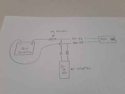
To test the sensor on the bench you will need a 1K resistor in the 12v supply to protect the SS41 in the PU. When you spin the paddle the voltage should fluctuate from around a low of 5v to a high of 10v. If you don't get that fluctuation, the sensor is bad. As far as bench testing the speedometer, I have never done that. From what I have read they rarely go bad. But I am curious about that and will let you know what I come up with. I hope the diagram helps, any other questions just ask I am glad to help. 20240114_091544.jpg
 
Last edited:
To test the sensor on the bench you will need a 1K resistor in the 12v supply to protect the SS41 in the PU. When you spin the paddle the voltage should fluctuate from around a low of 5v to a high of 10v. If you don't get that fluctuation, the sensor is bad. As far as bench testing the speedometer, I have never done that. From what I have read they rarely go bad. But I am curious about that and will let you know what I come up with. I hope the diagram helps, any other questions just ask I am glad to help. View attachment 64731
Thank you for this..
This way I'll know I have a good component to work with. If it fail, I will buy parts and rebuild it.
 
You are welcome. I would definitely get a working PU and then try it on the ski. I am going to guess that the gauges will work once you have a working PU.
 
I have tac, no idea about info looks just blank, low oil indicates, speed was not moving.
I was able to get a replacement speed sensor and speedometer. Which is why I'd like to test.
Since it's been minus 20 or so seems I have lots of time to plan ahead.
When my plus 20 weather arrives, I'll swap the sensor out with a working one, see if that works. If it's a yes, then I'll order parts to build a spare.
When I look at the wiring diagram for my ski, it looks like the sensor feeds both the info and speedometer which was why I was hoping to get a connect test circuit to test out both parts.
 
Yes, the digital and analog speedometers are in parallel, fead buy the same PU-YL pulse line from the Speedo sensor. I can draw you a diagram that I think would work to test your spare speedometer with a working speed sensor on the bench. If you want?
 
Give me a couple of days now to get you that. I need to verify the voltage to the speedometer itself.
 
Last edited:
Excellent how to write up. Since someone else already went slightly off topic, I will follow. My 97 GTI has an intermittent speedometer. Works fairly consistently from 0 to 20. Sometimes it will stay working up to 35. Rarely it will work all the way to flat out. However it mostly dies around 30 and will indicate 0. It will stay 0 until I slow down below 10 to 20 and then it starts indicating again. My first thought was connectors. I checked connectors and cleaned them. They seemed to be fine and no change in speedometer operation. I don't have experience will hall effect switches or zener failure modes. Do my symptoms sound like a dying component in the pickup assembly?

Brian
 
Hi Brian, yes I would say the SS41 is going bad. Had the same symptoms on 96 GTX we just got this fall. Speedometer would only go a little over 10 mph when we used compressed air on the sensor. Switched the sensor out with one I had fixed and the speedometer would run all the way up with the fixed one. Have you done a voltage check on the sensor yet? If you check it, I bet the voltage is not fluctuating enough to operate the speedometer correctly.
 
Last edited:
Thanks for the reply. Never did a voltage check. I did check the price of a sensor and decided it was working well enough :) Looking at the cost of an SS41 and a diode (my time is free since I am retired) and your excellent instructions , it is not working well enough now.
 
Thanks for the reply. Never did a voltage check. I did check the price of a sensor and decided it was working well enough :) Looking at the cost of an SS41 and a diode (my time is free since I am retired) and your excellent instructions , it is not working well enough now.
Let me know how it goes!
 
Back
Top