“I like to get everything on the ski working as it should.” I worked Mechanical/Hydraulic commercial airplane factory functional tests for the last few decades of my career. They assured that the planes were assembled and rigged correctly. Finding pushed back/bent pins, cut wires, crap relays, bad components, etc. could be challenging and I really loved that part of my job. And we never scrapped a multi-million dollar plane because we couldn’t find the cause. When I said oh well guess the GTI speedometer isn’t going to work, it has been eating at me ever since.
I did spend some time yesterday checking grounds because I really had no plan. Today I started looking at wiring diagrams. I really wish I had some functional descriptions so I understand how these gauges function. But I have an idea now of what is the most likely suspect.
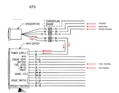
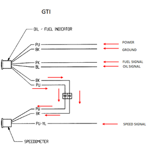
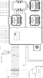
The GSX has pretty much the same speedometer and actually has labeling on the schematic. Purple and Black are power and ground to the gauges. Purple /Yellow is speed signal. Pink is fuel signal. Blue is oil signal. GSX has power and ground going first to the speedometer and then feeds those to the Info Center. GTI has power and ground going to the oil/fuel gauge first and then feeds it to the speedometer. My oil/fuel gauge is working with none if the intermittent stuff I see in the speedometer so the power and ground is making it that far steadily. I think chances are that the oil/fuel gauge power and ground feed though is most likely fine since that should be a simple solder connection. I looked at the power ground connector to the speedometer and it looked clean and good to me. To be sure I should measure that connector with a meter so I know it is coming through the oil/fuel gauge. It would be nice to know what voltage I am looking for. I also need to look in the big connector on the MPEM to see what the Purple/Yellow pins look like. If I can’t find anything, then it is the speedometer itself.
Does this seem like a reasonable plan? Any other ideas or experiences that would be helpful?