• This site contains eBay affiliate links for which Sea-Doo Forum may be compensated.

1997 787 No Spark-Possible causes

Status
Not open for further replies.
Krispy, I would rule out the battery issue first. By reading your posts you have 2 batterys that dont give an under load reading that is acceptable and will cause all kinds of intermittent issues and make it very hard to troubleshoot other problems. If the battery hovers around 10v underload the MPEM will start to do some funky things.

Maybe try hooking up a car battery from a non running car, with a set of jumpers, and see if you can reach closer to 11.5v under load. Make sure the car is not running!!

Got the battery thing sorted out, my AGM is holding good voltage under load. Going out to check mpem connections.


Sent from my iPhone using Tapatalk
 
The cdi won't turn on if the changing voltage was too low.

I have found in my experience it's tough to diagnose issues based on specs from the book. I've tested good 96cdi boxes and had some of the numbers not even close to the specs in the book. Using a good meter is also important... For that kind of testing your $10 harbor freight special isn't gonna cut it.

Now, the good news is if you are seeing voltage pulsing off the white wire that would lead me to believe the coil/connections are at fault. Unfortunately I use a test light so I don't know for sure you are getting enough voltage, but I would assume you would see none if the cdi on the mpem was dead.

Sent from my SGH-T989 using Tapatalk

Thanks, Was I testing it properly? Meaning, if I were to use a test light connect the clip to a ground and the probe to the white wire on the coil (while the wire is connected) I should see the light flash?

I can get a buddy to come by with a test light and re-test that.

Also, any feedback on the coil resistance testing? 1.2 ohms vs the .3x~.6x spec in the book? Is there a coil that should have 1.2 ohm?

Also, in the service manual I found this picture indicating that there was a second ground wire in 97 going to the battery (ala my 96xp)

Where would this wire have been connected? Do I need to put one back?

 
We are talking about this white wire right?
346.jpg


(On the left)


Sent from my iPhone using Tapatalk
 
yup...you have the top connector plugged in? I think you have some corroded connectors/wires and you are causing it to fail when you flip it over.
 
Yep, top connector plugged in. No corrosion to speak of.

347.jpg


My beeper is intermittent (so I do get 2 beeps with coil wire removed)

But still doesn't turn over when disconnected.

[video=youtube;5Ob4ZfI0PbI]http://www.youtube.com/watch?v=5Ob4ZfI0PbI[/video]


Sent from my iPhone using Tapatalk
 
See if all the wires match up between the harness and the inside of the box. Something in there isnt right. It should not function like that.

I think what is marked here as two white wires heading thru the connector as flip flopped....I dont have one to look at so you will have to figure it out, but that is my best guess.

 
Last edited by a moderator:
See if all the wires match up between the harness and the inside of the box. Something in there isnt right. It should not function like that.

I think what is marked here as two white wires heading thru the connector as flip flopped....I dont have one to look at so you will have to figure it out, but that is my best guess.


Thanks for the tip, I found something not matching the diagram.

If you number the pins on the diagram in your pic from bottom to top they would read like this:

1-empty
2-white
3-white
4-black
5-yellow, red trace
6-red, purple trace

However when I look at my connector (either side)

I see this:

1-empty
2-black
3-black
4-white
5-yellow, red trace
6-red, purple trace

Note the transposing of the blacks and whites.

351.jpg


Note I am counting pin 1 as the one without a wire on the bottom right, working clockwise around to 6.

The kicker to all of this is that the corresponding pins on the male side of this connector match!

So I thought perhaps the PO replaced the rear ebox AND harness from the wrong model, but as I followed the harness, it led all the way up to the mpem branching off in several places (charging coil, temp sensor etc). This means (to me) that the harness is original.

What do y'all think?


Sent from my iPhone using Tapatalk
 
as long as the white wire going to the coil matches up with the white wire heading to the mpem, and the grounds are hooked to the two blacks...it should work correctly.


The harness has to be correct...its a one year one model harness. The rear ebox is what I thought might not be jiving with the harness, being that it might have come off a different machine.

Im running out of ideas...but 100% positive that it should crank with the white wire unhooked.

I think theres a typo on the diagram...that wire going to the VTS is always been black...its a freakin ground...ground wires are black.
 
Last edited by a moderator:
as long as the white wire going to the coil matches up with the white wire heading to the mpem, and the grounds are hooked to the two blacks...it should work correctly.


The harness has to be correct...its a one year one model harness. The rear ebox is what I thought might not be jiving with the harness, being that it might have come off a different machine.

Im running out of ideas...but 100% positive that it should crank with the white wire unhooked.

I think theres a typo on the diagram...that wire going to the VTS is always been black...its a freakin ground...ground wires are black.

Well crap. I thought I had something there. I agree with you they both look like ground. I was looking at the diagram...it shouldn't matter what side of the coil the white wire is on should it?

Results so far:

Stator pickup coil (ohm's out as good)
Primary and secondary side of coil show good
Spark Plugs, Plug Boots, replaced and connections made.

We have an anomaly, and that is why the engine won't turn over when the white wire is unplugged from the coil.

So I have been poking around trying to figure out how the MPEM and other bits actually get ground from the battery. I have one ground wire coming from the battery going to the engine, how does the rear e-box get its ground?
 
On that machine it goes battery to engine/stator, stator to mpem, mpem to rear ebox.

Your abnormality is the big question.

Pickup/trigger...just ohming it doesnt tell you it isnt broken. You really need to pull those two wires out of the big connector and put a volt meter on them and crank. You should see a little flutter in numbers, if not, the pickup bracket has broke.

BUT...the 97s should have the updated bracket so its unlikely its broken.

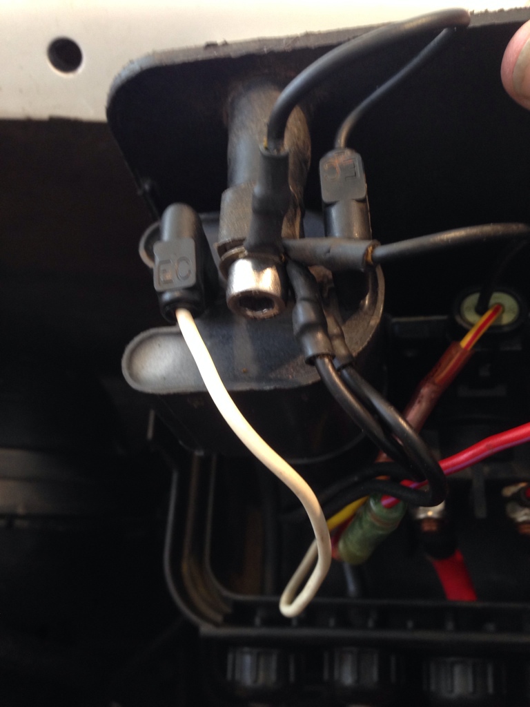
I physically inspected the stator cover and probed the sensor at the sensor. Bracket was in good shape without any debris around.

I HAVE NOT checked this resistance value at the MPEM wires, so possibly something could be shorting out or not making it to the MPEM.

What about turning the info center to RPM and trying to start the engine. If I see RPM in the info center then I know it is getting signal from the trigger coil. Seem legit?

As for the abnormality, I have a theory. Take the wiring diagram out here. I am going to be making heavy reference to it.

Symptom: When the white wire is disconnected from the primary coil lead, the engine doesn't turn over.

Theory: The starting solenoid doesn't have a ground source to close the internal low current switch (that sends voltage to the starter)

Theory: The white wire is serving as ground for the solenoid when connected ( through the primary side of the coil)

Theory: The solenoid switch side normally gets its ground from the coil base ground lug, the base ground lug serves ground (or gets ground from?) the MPEM pin 3-17 or through VTS to MPEM through VTS ground pin 3-2. **Note VTS is working** so it makes me think that VTS ground pin 3-2 is good.

Theory: The MPEM ground pin 3-24 is damaged/ bad connection between the stator housing and the MPEM.


Checklist:


Trigger coil checks

1. Check continuity between ground and wires on trigger coil (rule out a short of trigger coil)
2. Check resistance of trigger coil at MPEM plug (same as above)
3. Check RPM listed on gauge while starting engine (must have good pickup coil function to read RPM)

Grounding Checks
4. Check resistance at stator housing ground pin to battery neg terminal. (Ensure good ground for MPEM)
5. Assuming high resistance, relocate battery ground location to starter bolt (on rear engine mount cross brace now)
6. Check 3-24 (MPEM ground)
7. Check 3-17 (coil ground)
8. Check 3-2 (VTS ground, assuming OK now)

After tonight I hope to know if I have a grounding problem or a MPEM problem. What do yall think?
 
................................... oops wrong post.
 
Last edited by a moderator:
I

Checklist:


Trigger coil checks

1. Check continuity between ground and wires on trigger coil (rule out a short of trigger coil)
2. Check resistance of trigger coil at MPEM plug (same as above)
3. Check RPM listed on gauge while starting engine (must have good pickup coil function to read RPM)

Grounding Checks
4. Check resistance at stator housing ground pin to battery neg terminal. (Ensure good ground for MPEM)
5. Assuming high resistance, relocate battery ground location to starter bolt (on rear engine mount cross brace now)
6. Check 3-24 (MPEM ground)
7. Check 3-17 (coil ground)
8. Check 3-2 (VTS ground, assuming OK now)

Check results:

**As theorized above, the no start when white wire was off the coil was because it was providing ground for the solenoid, confirmed by adding extra ground between ground lug and battery, starts with white wire off**

1. Ruled out by #3
2. Ruled out by #3
3. RPM while starting =500

4. Stator housing resistance to battery 0.8 ohm
5. TBD (I don't know if 0.8 ohm is "low' or not.
6. MPEM ground is OK (from stator to MPEM main plug)

These next 2 are a little tricky. Since I have determined that the white wire on the coil was providing a psudo ground I had to perform these tests twice: a, with white wire disconnected and b with white wire connected

7a. Coil Ground is bad
8a. VTS Ground is bad

7b. (white wire connected) No ground wire harness side for pin 3-17 (led me to check 9)
8b. (white wire connected) VTS ground is good (functions)

9. Connector pin 3-17 to ground (continuous)

What do I think this all means?

1. No signal is coming from white wire while starting, in fact it is a ground source (Pin 3-18)
2. No ground source is coming from MPEM internally, it is "open" at Pin 3-17
3. White wire is the only source of ground for the coil (that is why the PO added the "extra wire" between the ground terminal on the coil and the battery ground)
4. No wiring problem (short or open) exists in this circuit.

5. I think I need a new MPEM.


[MENTION=41828]Minnetonka4me[/MENTION] here I come!
 
Krispy,
Great job diagnosing your no spark problem. Very detailed. You and Minnetonka laid it out very well.
Hope new MPEM works for you.
 
Krispy,
Great job diagnosing your no spark problem. Very detailed. You and Minnetonka laid it out very well.
Hope new MPEM works for you.

Yea, it is nice to have a forum where you can bounce your ideas off of other folks. Furthermore it is nice to be able to put it all on paper so to speak, by typing it out I am able to keep notes on what I checked and what still needs to be checked.

Minnetonka4me has been really helpful through this process. And the fact that he has a replacement MPEM makes it a full stop shop.

Imagine the kind of $ I would be spending if I took it to the Seadoo shop in town for this type of work, heck even if they did this type of work!

Lets just hope this fixes my no spark issue. If it does, I will open a project thread for the 97 gsx, if it doesn't.....:banghead:
 
I'm hoping the MPEM fixes your issue and you get that thing out on the water this summer!! Do you have any ideas or plans for this ski(after it's running of course). Cosmetically or aftermarket performance plans


Long live the 2 stroke Seadoo!
 
I'm hoping the MPEM fixes your issue and you get that thing out on the water this summer!! Do you have any ideas or plans for this ski(after it's running of course). Cosmetically or aftermarket performance plans


Long live the 2 stroke Seadoo!

I do, nothing too crazy with this one I think.

First plan is get spark at the plugs. Once I have that I move to fuel (there still is a grey fuel line connecting the carbs to one another) After that I should be running (good compression)

Then on to the jet pump and wear ring. Once she is water worthy and I have had preliminary sea trials I will move on to cosmetics.

No real aftermarket plans for this one, I do have a set of beach-house sponsons that were going on my 96XP but I think they were designed for the GSX so they might make it on here.

I will likely install some basic stuff like finger throttle. But this ski will be my "loner" ski, for my wife and others to ride. Or the one I use to tow back the 96xp when I blow it up! lol.

All details to come in the build thread once I get spark sorted..
 
Status
Not open for further replies.
Back
Top