• This site contains eBay affiliate links for which Sea-Doo Forum may be compensated.

Rectifiers

Status
Not open for further replies.

Eikari

New Member
So, after rebuilding a GTX 1996 and starting the break-in period, few problems have occured. The idling is very "loose" and i have to prime it well to have the engine running and i have to throttle it to keep it running. And sometimes it idles for a moment but when i just touch the throttle lever it stalls. All the fuses are in good condition and the stator has been checked with an AVO meter. The battery is 1 year old and i did a voltage with the engine on and off. Both read 12,68 volt which is not the correct reading according to the manual.

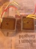
I took the rectifier out and compared it to another GTX´96 that´s also a rebuild project. They both look very similar, looks like some solderings have overheated. So both rectifiers gone bad or should i also look at other parts as well?

Also, one more thing. I did a compression test and both cylinders read 165 psi. Good or not good compression for a rebuild engine?

Einar
 

Attachments

  • jun 13 008.jpg
    jun 13 008.jpg
    376.2 KB · Views: 73
The compression it too high, it should be around 150psi, you may need a thicker base gasket, check the squish.

Check the AC voltage across the battery when the ski is running, over 1volt AC you need to replace the rectifier.

Lou
 
Ok, checked the voltage, AC. It measured 26,5 V with the ski running. Way over 1 volt! Also did another compression test, its done on trailer, not in water. The results should vary or no? 160 psi mag piston and 165 pto piston. Is this something to worry about?

I also checked the fuel system, the carbs have been rebuild and all the fuel lines were checked and blown with compressed air, also the fuel selector is as clean as it can be. I still have the grey lines but they will be replaced next month.
 
Sounds like a shorted or leaking rectifier diode, assuming your meter reading is reliable and not a cheap AC voltmeter, some of them are garbage.

This is a shunt type of stator regulator circuit as commonly used in many motorcycles, you can find many similar designs and troubleshooting methods on the internet to assist your diagnosis.
 
ok, thanks for the info. Its a quality AVO meter i have so the readings are accurate. I have ordered a new rectifier from SBT. so i´ll wait and see how it will go.
 
Ok, changed the rectifier and also the fuel lines. Cleaned the carbs and now it idles smoothly . Also no hesitation at acceleration.

But the 12V low light flashes from time to time. So i have checked the stator again. Between yellow wires and ground i get no reading
And between the yellow wires i also get no reading. So The stator is toasted?

If it is, then from whom should i buy a new stator? The price differs a lot, for example SBT has one for 225 $ and then i see on Ebay from Caltric for 80$. So, has anyone experience on the aftermarket stators?

Einar
 
If you need a stator get a good used one from minnetonka4me. Does the 12v. light flicker only at low idle, it so your idle may be set too low, if it only comes on at low idle I wouldn't worry about it.

Lou
 
Resistance to ground from any of the three stator leads should be OL or open.
Resistance from one to the other should be around 0.6 ohms and close or all even.

Running at idle should yield around 25 vac at idle and up to 75 vac at 5000rpm, That's the point where the stator is pretty much saturated.

A fully charged battery is around 12.6vdc at rest.

Charging voltage can go up to 14.4vdc

Any more and you could have a bad regulating part of the RR.

Charging a battery while connected can do this and you wouldn't know until running it.

This charging system is the same as for most motorcycles with 3 phase rectified/regulated charging systems.

There are better options for RR's

Such as: http://www.ebay.ca/itm/360635395542?ssPageName=STRK:MEWAX:IT&_trksid=p3984.m1423.l2649

That one is high end when compared to stock or what you would find on most bikes. Typically found on Yamaha R1's.

There are even better but just going to a basic one from a motorcycle would be better than stock, especially if you have any extra accessories.


Dirty or corroded connections don't help either.
 
Are you sure about the open stator? I thought you measured AC across the battery? That wouldn't happen if the stator was open, right?

The rectifier you replaced, it contains the regulator also? Sometimes aftermarket regulators can be set a tad too low, please measure your running battery voltage on both, AC and DC scale.
 
It is around 12,6 V DC idling(the same measurement is also with engine off) and it´s around 26 V AC at idle also.
 
Hi, Sounds like no change from original measurements.

Running 3500RPM, battery DC voltage should be greater than 12.8 and less than 15, due to shunt regulator circuit. I'm thinking 26 V AC across battery terminals must be AC current from stator feeding through rectifier, are you certain there are no miswiring issues, such as missing connections on regulator, and other grounds for example?

As you mentioned the stator is open, yet AC from stator is feeding through to battery? Not sure how that can happen, considering an open stator produces no current. Let's confirm AC is coming from stator? Disconnect stator(source of AC) from rectifier and recheck AC voltage at battery during running. If AC is no longer present, then stator was the source of AC at battery and rectifier is passing AC current. You can also check stator continuity and unloaded AC voltage at this time, should be 30 AC volts or so, engine running with stator disconnected from rectifier hopefully at least more than 14 volts.

You can also check rectifier to confirm it's okay, put your meter on diode check scale, current should flow in one direction only, from regulator input(yellow wires) to regulator output(red wire), only, not in reverse. It's this blocking action which only allows current to flow in one direction, converting the AC current from stator to DC current for the battery and accessories.

Regulator must have the following:

Yellow wires from stator connected to rectifier/regulator (AC from stator to RR)

Perhaps this ground is missing:
Ground to battery (-) for rectifier/regulator(black wire). (Regulator uses this ground as reference for control of output voltage)

Regulated output wire(red) fused, going to battery. (Regulator monitors this output voltage and shunts stator as necessary, to limit rectifier input voltage)

Also, so I may reference the proper schematic, which engine are we discussing, Rotax-717?

Thanks,
 
Its a 787. Are you talking about the ground that goes from the black electrical box to the battery?. After i changed the regulator/rectifier i noticed i got the same AC reading, 26 V. If the stator was not working i would get no AC reading?. So, the connections could be bad somewhere?

Einar
 
"Its a 787" - Thanks.

"If the stator was not working i would get no AC reading?"

Yes, I believe that's the case. Process of elimination. Disconnect the suspected source of AC (yellow stator wires, or regulator red wire) to eliminate this potential source of AC, then measure battery AC while running briefly. Regulator should not be passing AC to battery, remove regulator from circuit and check for AC, if still AC present then it's not coming from disconnected regulator.

"Are you talking about the ground that goes from the black electrical box ?"

All grounds, but specifically the black ground for the regulator, it cannot work properly without a proper ground which leads to battery "-" terminal.

FYI, I don't trust aftermarket rectifier/regulators made for jet skis, many people have reported dissatisfactory performance. There are many very good aftermarket regulators out there for motorcycles, and they are priced reasonably(not marine premium price), as well.
 
I did the diode test on the new rectifier from SBT. The yellow wires are two male plugs and one female plug . I get no current in either direction from the male plugs to the red wire and i get current in both directions from the female plug to the red wire.

I did the diode test also on two original rectifers of my GTX´s and they also show the same results..!

So i bought a faulty rectifier from SBT or is this diode test correct way to judge rectifiers?
 
Hi, This is an simple half-wave permanent magnet type generator.

I'm looking at the seadoo schematic now.

My belief is, there are likely just two rectifier diodes inside this RR, in addition to the regulator circuit, which we cannot static test.

I think we can test these two diodes though, to confirm they aren't shorted and pass current in one direction only. If they are defective, they will pass current in both directions, and thus will pass AC current from the stator.

You mentioned earlier, that the stator is open, and does not have continuity between the two male plugs. My belief at that time is this must be a mistaken measurement, but it's possible you performed the measurement correctly and actually do have a defective stator. In that case, the AC measured during running may have come from the ignition system and is a normal phenomenon.

Regardless, I know parts are expensive, so I prefer testing as much as possible before just changing parts. Seadoo claims the RR cannot be tested by static testing and this is true at least in part (although we cannot static test the regulator function, we may be able to static test the two diodes)

Obviously, if the stator is actually open, the regulator has no input and by default no output, thus your battery will not receive any DC charging current. In this case, the battery also won't receive any AC current from the regulator.

Assuming the stator is good(please check it again and look for any problems if it doesn't have continuity), then we can proceed to attempt preliminary rectifier testing:

In the case of testing the rectifier, the single yellow wire with female plug is the "center tap" of the stator windings and it connects through to the red output wire. The black wire of regulator would be connected to the anode of both internal diodes (common connection), and the two yellow wires with male plugs are the separate cathodes of the two diodes. Can you measure these in both directions with your meter set on diode test? (meter diode test: black wire and two yellow wires with two male plugs in both directions)

What are the results?

I hope you already have the wiring diagram of the seadoo charging circuit, if not then I can try to help you obtain it.
 
If you look at the first post in this thread, i had attached a picture of the rectifier. There are three yellow for stator and red for battery. There´s no ground cable on these rectifiers. I´m coming to think that it´s the stator. The Windings probably shortened and not generating sinus waves.

Einar
 
If you look at the factory schematic diagram of the charging circuit, it clearly shows a grounding connection to the RR.

My experience tells me every RR on every engine must have a grounding connection, otherwise it cannot measure the voltage potential across the battery, and thus could not regulate the output voltage.

Check carefully, there must be a grounding lug or connection on this regulator. The stator is a very robust coil of copper wire.
 
i have examined the schematic and i noticed the ground was not depicted with any color on rectifier. Could the housing of rectifier, bolted on a plate. be the ground?
 
"Could the housing of rectifier, bolted on a plate. be the ground? "

Yes, I think that's a pretty safe assumption. Make sure it's zero ohms from there to the battery negative terminal, it might be a long way back to the battery for those lose electrons with nowhere to go, a journey of many connections that are all corroding at a snail's pace.

By no means am I telling your the stator cannot fail, sometimes water can get into the housing and corrode the whole works to a powdery dust. In this case, you'd be lucky if the stator still worked.
 
Last edited by a moderator:
What about saltwater then? I know the previous owner had flooded it on sea. All the ground connection are tight and clean. So, I think we have ruled everything out except changing the stator. But this has been very informative thread. I can get a used one from a nearby workshop.
 
Yes, saltwater is very corrosive. You measured the stator for continuity, all three wires had nothing, no current flow with your ohmmeter.

You measured the stator and found no continuity, how confident are you of your measurement? That stator could be a heap of corroded dust inside. It's a bit of work to get to, but it might be necessary.

By the way, make sure to use lock-tight screw glue on the stator mounting screws if you do replace the stator, otherwise it will come lose and destroy the inside of the flywheel.
 
Status
Not open for further replies.
Back
Top