• This site contains eBay affiliate links for which Sea-Doo Forum may be compensated.

No thrust?

Status
Not open for further replies.

DonoBBD

New Member
Ok so some history on the boat.

1996 challenger with a single jet pump.
Brand new motor 800cc just about broke in.
Rebuilt carbs and motor and boat runs great.

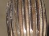
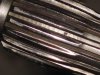
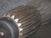
Had a great three days tubing with the kids and running the lake. When one after noon I had the boat a bit over loaded with kids and trying to get up on plain the nose of the boat was up in the air for longer than other times when still pushing a bunch of water we hear a big ZING.... the motor hits the rev limiter and I shut her down. Start the motor again and there is no load on the motor she just makes a loud zing like inside of a bell sound.

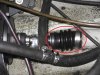
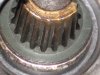
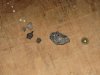
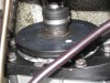
So we get the boat out of the water on the trailer. I look into the pump from under her and nothing obvious. Use a long screw driver and turn the impeller hard but I could. Brother in law says he can see the crank turn and I can feel the compression stroke and exhaust stroke of the motor from under the boat. Pull the screw driver out and ask my brother in law to fire or crank the motor over while I was looking at the pump. It turned free with a bit of a wobble.

Then I thought that we must have sucked up a stick or fish into the impeller and it came out. We back the pump back into the water again and same sound and no water through the pump with no load on the motor again.

Any thoughts on what could have broke or happened?

Cheers Don O.
 
You probably tore the splines out of the PTO. It could be from lack of grease, or a bad alignment after the new engine was installed.
 
It was all to be aligned but quality of work is only as good as the mechanic cares.

I am a handy guy where do I start?

I am looking for a better fresh water impeller as there is a few nicks in this one and rebuild the pump. Bearings wear ring and so one.

Is there a better impeller and fixed vein combo?

This may sound nuts but fuel mileage is 30% of my choices of the single motor and pump. Our lake up north here in Canada the fuel is $1.48 per liter. There is four liters in one US gallon so do the math.

Cheers Don.
 
Well pulled out the pump. Wear ring looks brand new. Did have a nice black stone roll out of the pump when I took it off. Splines all look great and no major wear. Pictures to be posted later today.

Now there was a black button on the end of the drive shaft that looked good. When I first pulled the pump and took a picture there was an extra hunk of black rubber in where the black button would need to seat.

There is a bunch of junk on where the pump would seal to the hull. Is there any chance that the pump was not on enough that the drive shaft is not into the splines enough? I would expect to see wear or grind marks. Pictures coming.

Don.
 
remove the shaft from the pto (located under grey cover). Feel/look at the spline conditions. If bad, i got extra one, if interested.
 
remove the shaft from the pto (located under grey cover). Feel/look at the spline conditions. If bad, i got extra one, if interested.


Grey cover? I have a black rubber cover just as the shaft comes into the boat then another shaft that gos to the motor. I tryed to pull that rubber flex cover back but there must be a trick to it. I have the two hose camps loose and off.

Any tips?
 
Grey cover? I have a black rubber cover just as the shaft comes into the boat then another shaft that gos to the motor. I tryed to pull that rubber flex cover back but there must be a trick to it. I have the two hose camps loose and off.

Any tips?

post a pic
 
Some pictures of the impellers splines and drive splines. They look great. Here are the stones I found in her.

Don.
 

Attachments

  • IMG_0606.jpg
    IMG_0606.jpg
    47.8 KB · Views: 18
  • IMG_0616.jpg
    IMG_0616.jpg
    39.2 KB · Views: 19
  • IMG_0609.jpg
    IMG_0609.jpg
    36.2 KB · Views: 15
you'll need to retain those driveshaft bumpers.

The first pic, thats your carbon ring assy. The steel collar, the carbon ring rides against, you need to push that toward back of boat, to expose the steel clip/o-ring. Remove it/roll it up the shaft, toward the motor, and that will "release" the driveshaft, so yuo then can pull the shaft from craft.

There should be a grey cover, that covers the "pto"...white wheel attached to the motor.

This guy. Guessing the white ring is gone and this is the PTO. I am guessing it needs to be marked for balance? Looks like a hole drilled in it for balance.

Thanks so much for the how to.. to get the shaft out. I bet it is striped in there so how.

Cheers Don.
 

Attachments

  • white ring but black.jpg
    white ring but black.jpg
    49.9 KB · Views: 23
Ok popped out the drive shaft and she is shot. The spines seem to be totaly dinked. Note picture.

I am trying to shoot a picture of the inside of the flywheel to see if they are good. I am guessing these motors come with the flywheel on them?

Should the carbon wear ring fit tight on the shaft or dos it make the seal on the stainless collar front surface to surface not tight on the shaft? The inside diameter of my carbon ring is much bigger than the drive shaft.

It looks like I will need a drive shaft, O rings for the drive shaft for the stainless carbon ring keeper, two O rings for inside the stainless keeper, and one button stopper for the end of the drive shaft motor side. (was not one on there could push the drive shaft back in and feel steel on steel when working the shaft in and out.)

Where can I find these goodies. These things are surprisingly easy to work on. Well other than climbing into the back of them.

Cheers Don.

EDIT: hear is a thought. When I felt into the flywheel the splines for the drive shave to mesh into seemed quite short like .25" of good spines. Now that black rubber bump stopper that is suppose to be on both ends of the drive shaft is about .25". What if that not being in there would let the drive shaft move into the motor more putting the good gear cut groves in the flywheel lower on the rounded groves of the drive shaft. Then sucking up that stone totaly dinked splines. Look at my first picture of the drive shaft you can see how the most damage is at the rear most part of the drive shaft more to the jet side of the splines.


I know this is the problem because the rubber seal that clamps to the drive shaft and then to the flywheel inside there was a birds nest of spun rubber. This I can see is from the shaft staying fixed and the flywheel spinning the rubber seal on the drive shaft. There was a nice pile of spun rubber in there.
 

Attachments

  • wiped drive shaft.jpg
    wiped drive shaft.jpg
    47.6 KB · Views: 17
  • wiped drive shaft2.jpg
    wiped drive shaft2.jpg
    59.3 KB · Views: 15
  • good drive shaft end.jpg
    good drive shaft end.jpg
    36.2 KB · Views: 12
Last edited by a moderator:
measure the driveshaft. The steel collar is good, just lap it on wet/dry paper. The carbon ring "floats" around drivewshaft. If anything, replace it. If you dont have the c-clip or o-ring, to hold the steel collar in place, got o-ring as well. Got both driveshaft plugs too...pto/impellor sides.
 
Status
Not open for further replies.
Back
Top