1999 Seadoo GTX Limited No Spark

Note: This site contains eBay affiliate links for which SeaDooForum.com may be compensated

dmontero

Member
Hello All - I'm not getting a spark on my 1999 Seadoo GTX limited. Here is the summary:
- Battery is new and strong
- I get two perfect beeps when I put the key on
- Engine turns over and starter goes just fine
- New sparks


What I Have Done:
- Tested grounding and continuity on everything I could feel pretty confident
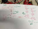
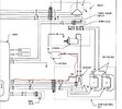
- I studied the wiring diagram and confirmed everything is where it needs to be unless there is a ground that is not on diagram.
- Tested resistance between the two Ignition Coils and got 0.2 (spec calls for 0.33-0.62). Could this mean bad...?
- Everyone seems to say that it probably isn't the ignition coils if the both are out because it is unlikely.
- Resistance at the two spark cables is 18.84 which is out of spec (spec calls for 8.4-15.6 on the secondaries). What would this mean? I cut them back and still 18.84
- My spark caps didn't look great. I tested continuity on them and literally got 0. This surprised me and could theoretically be the issue but I would be really surprised... in any case, I have two new ones on order.
- I am still confused at how I can test the MAG/Trigger Coil without removing the cap. If I pull the 6-pin harness out, do I literally put my leads on the pins in the harness?? It seems like that would not tell me if the trigger coil is bad or good because the trigger coil is literally not connected to it. There is no way I get my leads into that harness accepter on the cap without removing it.
- is there any way to bypass the trigger coil/magneto to see if they are bad and the MPEM is good? I know we can never test if MPEM is bad, but any way to confirm it is good?
- Obviously doing what I can before I remove that MAG cap or order the new MPEM......

Thanks all!
 
Thanks Racerx - I think its time for me to test a new MPEM.

I drew up a quick schematic to keep my head straight and notes as I went through this because I am not very electrically inclined. Maybe my diagram will spark a thought from someone?

Inputs
In any case, as you can see I am pretty confident in the inputs to the MPEM. Trigger coil is within spec Vac and ohms. I assume the magneto is good since I get the pulsing voltage at the trigger coil. I figure I won't worry about timing until I actually get a spark. I also pulled the ohms at the MPEM sockets for the trigger coil resistance and was still in spec. I couldn't test voltage here because harness needs to be plugged in. Key is good as I get the two beeps. Start button is good because the starter works.

Outputs
I put the 6pin harness I made in line with the rear electrical box to test voltage at the white output wires and ignition coils. I got 1.2 ohms across the coil terminals which is out of spec (spec is .34-.62 ohms). The little connectors back there were the connecting the white wires to the coils were very corroded so I am going to replace these. I am also getting zero volts out of those white wires which seems to be the main issue. Should I be getting a constant 12v or a pulsing voltage for spark? Could the heightened resistance be stopping this? Obviously I would love to know if I could test if it is the MPEM at this point but not sure if replacing those connectors would do much.

Brand new sparks and spark caps. Cut back the secondary windings. Resistance across secondaries is good.

Let me know what you think!!
 

Attachments

  • 1999 GTX LTD electrical diagram.png
    1999 GTX LTD electrical diagram.png
    2.4 MB · Views: 35
I would start by following the 2 white coil wires to the MPEM harness connector. Open up the hardeness connector and gently squeeze in the female connectors on those 2 white wires so that they fit slightly tighter on the MPEM pins. The white wires I believe should have power most of the time to charge the primary winding creating the electrical field in the coils. The MPEM will momentarily break the power to those wires causing the electrical field to collaps sending high voltage power out the secondary windings down the plugs wires to the plugs. Most likely issue is those pin connections I've mentioned and it cost nothing to start there before spending big money on a MPEM.
 
Can you check the mpem male connectors with a multimeter while the harness is unplugged? Or does the harness need to be plugged in to trigger voltage output?
 
If you unplug that connector (Connector #3) from the MPEM then you will also unplug the battery source (see diagram-red line). Have you downloaded the service manual so you can view the wiring? Did you take apart the connector and gently tighten the female (plug side) side to ensure good contact with the MPEM pins? I keep going back to the pins because we had several skis with this issue, this it's likely common for others as well.
 

Attachments

  • 99 GTX Plug3.JPG
    99 GTX Plug3.JPG
    102.5 KB · Views: 28
Yea very familiar with wiring diagram unfortunately. Didn’t review it before asking lol nice catch! I’ll check out the pins but they really all do look perfect
 
With pins it's not about how it looks. Each in our experienced both the male and female sides looked perfect but was in-fact an issue. This may or may not be your issue, but it's certainly worth checking out before spending money that may not need to be spent. Be sure to respond with your results whether is was an issue on yours or not. Curious, what state are you in?
 
please before you buy a new MPEM pull the caps back off and lay the bare spark plug wires on a non conductive surface about 1/2 inch apart and crank the engine. Is there a nice blue intermittent spark?

if yes?
that means your coil , trigger, wires, grounds, and MPEG are most likely fine!
 
if your caps tested 0 that means no resistance (which is certainly better than say 5M ohms which is near infinite resistance)
 
In CA. Definitely checking the pins this weekend per your recommendation. I’ll keep you updated.

I will also check without the caps on. Pull both or one at a time?
Wouldn’t 0 ohms mean no continuity? I bought new caps just in case
 
0 ohms is perfect connection, no resistance. Open, n/a, or very high resistance could mean open depending what meter you are using.
 
Update on a few things:
- There was a bit of corrosion on MPEM connector 3. Pulled the MPEM, sanded the corrosion off gently and applied contact cleaner to all connections. Racer - pulled the covers off of the harnesses and gently tighten all females.
- In the rear e box I replaced the corroded white connectors
- I am pulling a constant 2.2V in line with the white wires. This is when I put a 6-pin harness in and capture the voltage BEFORE the e-box and I put my other test probe on ground.
- I am also pulling a constant 2.2V at the end of the white wire female connector (when unplugged from the trigger).
- When I try and take a V reading with the white wire plugged in (I sneak the test probe onto the remaining metal at the trigger) I get 0V. This seems weird.
- I have two ignition coils. When the manual says to check resistance at trigger coils, does that mean pulling resistance from the male primary side between both? If so I am out of spec here.
- Only one of my ignition coils has a ground wire. Does the other one need a ground wire? Not a lot of good info on grounding in the manual
 
The manual says you should see 12v. But is that between ground and white wire? Because it referenced the RFI model where you take the test between red & whites but I am not sure what the red is for RFI's even after looking at the wiring diagram
 
This morning I was getting .5v at the ignition coils. Then I added a ground wire from battery negative to rear electrical negative post. Now I am getting 1v at the coils.

Basically I have determined that I am just getting inconsistent V at the coils. Could it be due to poor grounding? Trigger coil Voltage checks out going into the MPEM
 
I pulled the mag cover off today and the trigger could tested perfect and looked extremely clean.

Can any one confirm what voltage you should see at the white wires at the ignition coils? Today I was seeing 2-2.2v. What should the voltage do at the white wire when you are starting the ski up?
 
it's been a bit since I've been on the forum, so I'm catching up on your testing.
The white wires should be delivering 12v to the coils. Sounds like this is the root of the problem. Did you check voltage on the white wires at the MPEM? If you have 12v there and not at the other end then that wire is corroded or damaged somewhere, possibly hidden within the insulation.
Both coils should have be grounded, One with 2 black ground wires, the 2nd through the metal bracket both coils are mounted to, make sure there's no corrosion where the coils mount.
Declaration -"at your own risk" You should be able to test fire the coils and fire the spark plugs manually.
-First disconnect the battery from the factory seadoo wiring. Then isolate the coils from the seadoo electrical system as not to risk damaging anything on the skis electrical system.
-Disconnect the two factory black ground wires and the two factory white primary coil wires. The coils should now be electrically detached from the ski.
-Run a ground wire from the battery to the metal on the spark plug, such as the threaded area.
-Run a second ground from the battery to the coils' metal mounting bracket to provide them with ground.
-Take third wire and place it on the positive terminal on the battery. The other end will be momentarily touched where the white primary wire was on the coil (white wires should be detached at this time) but only for a moment and then removed. Upon removing the contact the coil's primary field will collapse and should release a spark through the plug.
 
Last edited:
Update on a few things:
- There was a bit of corrosion on MPEM connector 3. Pulled the MPEM, sanded the corrosion off gently and applied contact cleaner to all connections. Racer - pulled the covers off of the harnesses and gently tighten all females.
- In the rear e box I replaced the corroded white connectors
- I am pulling a constant 2.2V in line with the white wires. This is when I put a 6-pin harness in and capture the voltage BEFORE the e-box and I put my other test probe on ground.
- I am also pulling a constant 2.2V at the end of the white wire female connector (when unplugged from the trigger).
- When I try and take a V reading with the white wire plugged in (I sneak the test probe onto the remaining metal at the trigger) I get 0V. This seems weird.
- I have two ignition coils. When the manual says to check resistance at trigger coils, does that mean pulling resistance from the male primary side between both? If so I am out of spec here.
- Only one of my ignition coils has a ground wire. Does the other one need a ground wire? Not a lot of good info on grounding in the manual
From the manual regarding the white primary wires on the coils'

1656917814218.png
 
Last edited:
Racer thanks for hopping back in!

There is only one ground that hits the metal bracket and presumably grounds both coils. Either way, still only getting 2v at end of white wire when I unplug it from the coils.

I have continuity in both whites but how do I check for 12v at the mpem without unplugging it? I know someone else said to try and probe through the front of the mpem harness but that worries me.

While I want to bench test the coils, I want to figure out the 12v at the coils first before I go potentially screw something up with the coils..
 
Do it by the process of elimination. Unplug the wires at the coils and the MPEM. Run battery voltage from one end (ie at the primary white wires) and measure the voltage at the MPEM harness-side plug. There should be no to very little voltage drop. If that's successful, then the MPEM is not providing the required voltage. You can have continuity and still have voltage restriction.
 
Last edited:
Back
Top