• This site contains eBay affiliate links for which Sea-Doo Forum may be compensated.

1997 GTX off season rebuild start.

AquaEye

Premium Member
Premium Member
This thread is born out of the post "97 GTX. Normal engine noise?" posted June 24, 2025.
Have hoist, low profile shop cart, sling arrives next week. Pull engine & then to the 1st order of business, pull oil pump & bench test using factory procedure for validation @ 1,500 rpm. Marks will be aligned to simulated idle setting event so as to confirm .017-.087 ml @ 1,500 rpm for 30 seconds out of one port only or 1.74 ml for both ports using lab scales, 3ml lab syringe as tools. Question, what is the amount of oil dispensed @ w-o? Cant find that anywhere here, YT or factory manual.
Imo, idle oil amount to me is more important, right(?) I want to keep the oil pump. Been pre-mixing for decades & I'm tired of it & besides, I trust Mikuni.
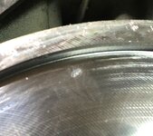
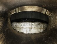
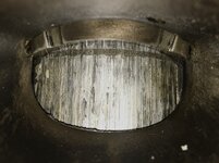
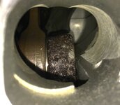
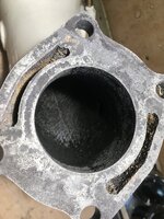
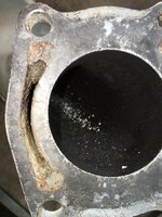
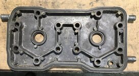
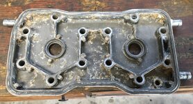
Next, pulling cylinders/head. Using dial bore gauge, two bloodshot eyes, some lessons learned from rebuilding 2 stroke Kawi's & Yami's & with only 40+ hours on the engine & some clueless do-da luck, I might squeak by with just honing...or not. Piston>pin>bearing, very close inspection.
Time frame for this initial start/determination?
No hurry, still have plenty on my plate & a life to live for the rest of this season but I should have results on the oil pump bench test in a couple of weeks.
Will post with a few pics & maybe a video or two @ that time.
FYI: This is my 1st rotary ROTAX build & thou confidence is not high (out of my element, sort of ), you guys have been pointing me in the right direction. Many thanks now & more to come.
IMG_3706.JPG
 
Just run the oil pump at close to 1500 rpm and make sure oil is coming out of it.
I honestly don't worry about them. In 35 years of working on these and tens of thousands of threads here I think I only ever heard of 1, that is one, ever failing.
 
Just run the oil pump at close to 1500 rpm and make sure oil is coming out of it.
I honestly don't worry about them. In 35 years of working on these and tens of thousands of threads here I think I only ever heard of 1, that is one, ever failing.
I have very good fortune with Mikuni products across the board but still can't ignore my nature to always dive deeper, to validate. It's who I am.
 
I have very good fortune with Mikuni products across the board but still can't ignore my nature to always dive deeper, to validate. It's who I am.
I would like to pick the brains of a few experienced operators of the 787. Focusing on the oil pump relationships here.
In a "perfect world" of engine integrity & comparing the PTO & MAG components so as to maybe reveal a trend(?).
*Which of the two spark plug always seem "sootier" or seem to be discernably different from the other?
*Same question of the rave valves?
*Which of the two cylinders always seem to have the higher compression?
*Has anybody disassembled an oil pump? Focusing on the separation distance of the two ports within the pump. (a pic would be nice).
 
They should be the same in compression and cleanliness.
It is a dual carb engine so you can tune them both to be the same. Oil pump provides the same oil to each cylinder.
 
They should be the same in compression and cleanliness.
It is a dual carb engine so you can tune them both to be the same. Oil pump provides the same oil to each cylinder.
A few other " experienced operators of the 787" from other forums are noting subtle differences in that "perfect world" that's pointing to a trend, a commonality. Apparently, I'm not the only one that drills deeper & that's refreshing.
Have yet to dissect an oil pump for the particulars but I'm patient.
Yep, learning as I go forward.
 
Build it and run it. There is no carb tuning just proper set up and testing using the right parts (Read the Carb Thread and follow it). I've have personally had the oil lines I purchased fall to pieces in a matter of a couple of months, vendors very optimistic as to the quality of the crap they sell... it was suppose to be Tygon and it was an oil line that failed. ( I got lucky and it only destroyed the piston on the air compressor. I don't know what everyone is using today but now I cut a piece of the line I'm using, drop it in laquer thinner for 15 minutes. I also test it by lighting it on fire to see what happens. The junk usually falls apart after 5 minutes in laquer thinner.

I prime the oil pump using a drill motor in reverse. Check, check, check for leaks on the oil system, especially the oil tank at the seam. These skis are sneaky. Good Luck !!
Hi @etemplet , I use the the OEM line from BRP, it’s clear so you can watch them fill up, you know they are exactly the right size which is super tight by the way and the quality should be good enough to last 20 years. They come in 1500 mm lengths so enough to do 2 to 4 machines depending on which machines. If you need a part number let me know, I have all my receipts in a file so easy to find.
 
Burt send that part number.
The part number I have on my last invoice is 219704404, that number had superseded roughly 6 part numbers. Next time I order, I think I’m going to order 4 packages of it, I’m going to start stock piling some parts just in case some of them start getting discontinued. After all, my 95XP is 30 years old now.
 
The part number I have on my last invoice is 219704404, that number had superseded roughly 6 part numbers. Next time I order, I think I’m going to order 4 packages of it, I’m going to start stock piling some parts just in case some of them start getting discontinued. After all, my 95XP is 30 years old now.

I got an azzload of parts over here. LOL I used to order 5 of everything for spares. Yea I agree on the OEM hoses they lasted a long long time.
 
I got an azzload of parts over here. LOL I used to order 5 of everything for spares. Yea I agree on the OEM hoses they lasted a long long time.
For me, I will need something, but to get the free shipping have to order 99.00 or more so I always pick up a few extra parts, I worry that someday these parts may not be as readily available. Right now it seems that some of the young guys are into these 2 strokes but I wonder what it will be like in 10 years from now? Maybe by that time the sparks will be old enough and cheap enough that maybe some will go that way?
 
For me, I will need something, but to get the free shipping have to order 99.00 or more so I always pick up a few extra parts, I worry that someday these parts may not be as readily available. Right now it seems that some of the young guys are into these 2 strokes but I wonder what it will be like in 10 years from now? Maybe by that time the sparks will be old enough and cheap enough that maybe some will go that way?
Seadoo is discontinuing parts on these all the time, stock up while you can.
 
I'm more worried the govt will outlaw our 2 smokes....its already started in California!
Without getting too off topic.
It was a concern years ago, like 20. I'm not worried about it and live in California. The only banned them on a couple lakes and no new talk about it. I think we are safe until we run out of repair parts. :)
 
And life got in the way this Monday so I started the engine removal & partial teardown process yesterday & a lot of answers to my concerns. First set of pics, well established rust on crank, PTO side & very discernable & audible play @ rod/crank. Yeah, no mystery here. Next set of pics, MAG. Deep gouging of piston skirt & ring seized/melded into groove.
Further inspections, probably no flush performed ever during it's brief life (40.3hrs). Water passages clogged to 40%.
Of no matter, I've dealt with worse.
Next set of pics, the rotary valve. The small divot(?) in the pics, fingernail does catch but slightly, very negligible rise. The plate has a burnish spot & very very small pitting (maybe 20% of surface area).Minor scoring on both sides but nothing catches.
This being my 1st rotary, I have absolutely no clue on what passes for integrity of rotary components. Really would appreciate some input/opinions.

Mind you, the pump liner was completely destroyed/missing. That being said, it's no mystery that water circulation was compromised. If it ran like that for an extended time, overheat.
p.s. The oil pump test is on hold, probably do that @ "tail end" of repair.
 

Attachments

  • IMG_3722.JPG
    IMG_3722.JPG
    782.6 KB · Views: 21
  • IMG_3727.JPG
    IMG_3727.JPG
    1.1 MB · Views: 15
  • IMG_3726.JPG
    IMG_3726.JPG
    748.1 KB · Views: 14
  • IMG_3724.JPG
    IMG_3724.JPG
    981 KB · Views: 14
  • IMG_3723.JPG
    IMG_3723.JPG
    652.3 KB · Views: 15
  • IMG_3721.JPG
    IMG_3721.JPG
    572.7 KB · Views: 15
  • IMG_3719.JPG
    IMG_3719.JPG
    641.2 KB · Views: 16
  • IMG_3716.JPG
    IMG_3716.JPG
    636.2 KB · Views: 14
  • IMG_3715.JPG
    IMG_3715.JPG
    749.2 KB · Views: 15
Further teardown.
Mind you, this engine has 40.3 hrs.
MAG piston(6pics)
Notice bottom ring pin location within ring gap. Take note of top ring pin location, NOT in ring gap. Yeah, no mystery here. Cylinder walls have deep striations. "Just" beyond honing, bore next size up. Piston pin extraction was very labored even with pin extractor. Lateral/vertical play of
con rod( by comparison with PTO), compromised. Mic connecting rod/pin hole later.
IMG_3753.JPGIMG_3754.JPGIMG_3740.JPGIMG_3743.JPGIMG_3745.JPGIMG_3755.JPG


PTO piston, no surprises here. Pin extraction was relatively easy. Scoring along skirt. Cylinder wall had slight burnishing @ bottom & negligible scoring. Established rust on crank counter weight. Lateral/vertical play of con rod easily acceptable.
The pic of the cylinder head dome(s) & piston tops, is this indicative of a motor of 40.3 hrs using factory recommended syn oil & "supposedly" correct carb settings?
FYI: Previous owner had receipts & work orders performed by Lufkin Sea Doo dealership all the way up to 2012, After that, crickets.
Craft never saw salt water. The owner had his own lake in his back yard along with 4 teenage boys that had access to "professional" tools.
Yeah, this engine was cracked wide open after dealership work & before my purchase. Might explain the "low hrs", huh?
IMG_3736.JPGIMG_3737.JPGIMG_3735.JPGIMG_3756.JPG
 
The cases could be fine as long as that circular mark in the middle isn't enough to catch a fingernail on. You can't have a connected path at the intake ports like a groove that would let the intake signal move from one port to the other.

That engine was run lean by the dry carbon on the piston crowns and seizing of the pistons and rings. There is no evidence of piston wash which is what you want to see on a happy 2-stroke.
 
Had a gallon of Rydlyme marine biodegradable de-scaler left over from a previous outboard service & thought I would give it a shot on some components. The usual method is to circulate thru the outboard as per manufacture so I "rigged up" circulation bucket & cycled for a couple few hours. Works great on outboards but not so much on individual, separated components but it work none the less. Used the 1 to 1 ratio.
Before & after pics.
The biggest improvement was the head pipe. Even thou the pic doesn't do it justice the debris left @ the bottom of bucket was just over 3 oz. Channeled flow along with the velocity was probably the advantage.
Anyway, had time to kill & thought I give this a shot.
Still going to do the vapor hone.


Attachments

  • IMG_3787.JPG
    IMG_3787.JPG
    467.1 KB · Views: 15
  • IMG_3786.JPG
    IMG_3786.JPG
    628.6 KB · Views: 13
  • IMG_3795.JPG
    IMG_3795.JPG
    668.5 KB · Views: 13
  • IMG_3800.JPG
    IMG_3800.JPG
    862.8 KB · Views: 13
  • IMG_3793.JPG
    IMG_3793.JPG
    699.9 KB · Views: 14
  • IMG_3792.JPG
    IMG_3792.JPG
    773.5 KB · Views: 15
  • IMG_3785.JPG
    IMG_3785.JPG
    664.5 KB · Views: 15
  • IMG_3796.JPG
    IMG_3796.JPG
    771.1 KB · Views: 15
  • IMG_3789.JPG
    IMG_3789.JPG
    772.5 KB · Views: 21
Last edited:
A few pics of before & after so as to show the result of "beaching" your craft or shallow water starts. The tuned pipe that I ran de-scaler thru also had similar debris along with dissolved scaling & rust.
 

Attachments

  • IMG_3832.JPG
    IMG_3832.JPG
    1.1 MB · Views: 16
  • IMG_3833.JPG
    IMG_3833.JPG
    862.3 KB · Views: 16
  • IMG_3831.JPG
    IMG_3831.JPG
    990.5 KB · Views: 16
  • IMG_3835.JPG
    IMG_3835.JPG
    895.8 KB · Views: 17
Casting flaws, both cylinders. Pic 3838 flaw is a little too close for comfort. No mystery there on re-assembly.
IMG_3837.JPGIMG_3838.JPG
 
Casting flaws, both cylinders. Pic 3838 flaw is a little too close for comfort. No mystery there on re-assembly.
View attachment 68330View attachment 68331
That is from corrosion, not casting flaws.
A little 1211 on the new gasket will have it sealing perfectly.

Since you are very meticulous I encourage you to test the squish and get the correct thickness base gasket if you can still find them, you will get a nice little boost in performance as opposed to the generic "6-hole" gasket that all the gasket kits ship with.

And a little more technical info for you from Group K....

Precision Top End Assembly of the Laydown Rave Motors – Squish clearance, the distance between the piston crown and cylinder head at top dead center, is an important specification that is minded by the Rotax factory as well as all high performance engine builders. The Sea Doo manual offers a fairly wide tolerance for squish clearances, however most engine builders prefer closer clearances to help stave off detonation. Most builders measure the squish clearance by sticking a piece of solder through the spark plug hole toward the outside edge of the bore…then momentarily touching the start button so the piston makes several strikes at the solder. This allows the solder to be crushed to the exact thickness that shows the “squish clearance”. At Group K we make a point to take these “squish clearance ” measurements over both ends of the wrist pin. This minimizes the piston’s ability to “rock” and show an inaccurately large clearance. We also take these measurements over both ends of the wrist pin, on both cylinders, to assure uniform clearances. In a perfect world, all four squish measurement will be within .002″ – ,003″. Unfortunately, we have been observing everything but uniform clearances. This is a matter we do not take lightly, since accurate squish clearance is the only way to assure correct deck height setup (a function of the base gasket thickness).

Immediately, we though that the variations were caused by incorrectly cut squish bands on the cylinder head…not so. The bands had a uniform depth and perfect center to center location. We then suspected variations in the locations of the cylinder mounting holes in the crankcases, but they also measured perfectly. In the end, we found two items that caused the variations. The first was that the distance between the two cylinder bores can vary greatly, depending on the assembly procedure. That is, there can be almost 1 mm variation in the center to center distance of the bore diameters based solely on the random location during assembly. Secondly, the cylinder head itself has a great deal of movement leeway (both left to right, and forward to back). All these variations of fit take place because the cylinders and cylinder head are not located to one another with “dowel locating pins” (as most Kawasaki engines are). The absence of these locating pins allows for alot of movement leeway, of both the cylinders and the cylinder head. That results in broad variations in squish clearance measurements. Installing dowel pins is a questionably wise solution because of the great risk that the exhaust manifold faces would not be perfectly parallel (that would cause bore distortion when the exhaust manifold is torqued on).

For now, our best solution is to recommend a “Precision Assembly Procedure” that will make for minimum variations in squish measurements.

Our procedure is based on the following information. The cylinder base bolt patterns in the cases are located 132mm (5.196″) apart. The standard bore diameters of the cylinders are 82.0 – 82.08 mm (3.228″ – 3.231″). This means that the inner distance between the two bores of the torqued on cylinders should be between 49.91 – 49.98 mm (1.965″ – 1.968″) These last measurements can be taken quickly and easily with a set of dial calipers after the cylinders have been torqued on. In most cases, we have found that you can hit this spec range if you install the cylinders as close together as possible. It bears noting that we have seen engines where the water jackets of the cylinders touched before we could reach this specification range. We literally needed to belt sand some material off the aluminum cylinder casting to get the correct spec. Cylinders like this are certainly the exception (not the rule), but they do exist.

Once the cylinders are installed with the acceptable center to center distance, it becomes apparent that the cylinder head itself can move about 2mm (.080″ in any direction over the tops of the bores. This location will also have a profound effect on squish clearance measurements. We got out best results by matching the edge of the head casting, all the way around, as closely as possible to the edges of the cylinder castings. While this doesn’t sound very precise, it works surprisingly well. After torqueing on the head, you can take your four squish clearance measurements to determine if the head needs to be moved slightly one way or the other…it’s not really as tough as it sounds.

Does everyone one who assembles a Rave top end “have” to go through this whole procedure…not necessarily. However we strongly recommend this procedure to anyone preparing a high output Laydown Rave motor. If you find a wide variation in the squish clearances of your freshly assembled engine…it could certainly avert some problems before they get started.
Yes, I'm starting to lean to that "corrosion" camp also. With the motor having only 40.3 hrs, I "knee jerked" to casting flaws but with the evidence of little or no flushing by the previous owner & other signs of neglect, corrosion is the issue.
Thanks for the Group K article, very informative.
 
Forward thinking so as to pin down & clarify a procedure that will occur later down the road. I'm having trouble getting my head around on concerning "break in" oil type. Scoured the forum, un-determined @ this point.
For decades I've used Group K for the serious machine work on the half dozen or so 2 strokes (yami, kawi). The honing I've regulated to the machine shops in the county if that's all that is needed. I've always used Bel Ray T2 premix (mineral) for break in>syn later or customers prerogative on the oil after the break in.
This being my 1st rotary valve, oil injected 2 stroke, I feel compelled to "pick the brains" of the SD 2stroke enthusiast who have "been around the block" a time or two. Good detailed & cogent instructions on procedure on this forum but it always seems to involve the use of synthetic oil(s).
There's the dis-connect.
So w/o all the procedures for oil injection that I have learned from this site, let's drill down further & do the "Pro's & Con" of using mineral -vs- syn during break in knowing of the pia logistics that that will come from going to mineral to syn but I prepared for that. Or maybe I'm overthinking it...:oops:. That bottle of single malt scotch says, maybe?
And of course, I will get in touch with Harry @ Group K to get his 2cents.
One other thing, as in the past I've always used forged coated pistons on top ends.
Thoughts on applying it to this build?
 
Back
Top