A look inside the "787"

Note: This site contains eBay affiliate links for which SeaDooForum.com may be compensated
Status
Not open for further replies.

seadoosnipe

Premium Member
Premium Member
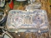
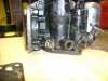
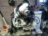
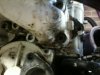
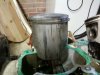
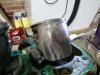
In the days to come, I will be posting pictures that I have with some short opinions and manual suggestions on the working parts of the 787. The motor you will be looking at was inside a 1996 Challenger that sunk and the engine was flooded all the way up to the time I got it, which was about one year.
Enjoy and if you have comments or questions, feel free to create a thread in the proper forum with a reference to the post number. If I'm not getting to a part your working on fast enough, please PM me and I'll work on it as fast as I can.
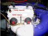
First, there have been some members looking for the difference between the DESS (digital electronic security system) and the standard 12 volt on/off (kill switch).

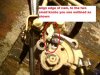
The DESS post and lanyard cap started it's public use in between the 1995-1996 model skis/boats. I think everyone knows what that little forked, finger looking thing was for, to keep the kill switch pulled out and the lanyard attached to your body so that if you fell off, you'd kill the engine.

I remember the old Kawa's that when you fell off, they would slow down and just do circles. Well, seems like I always fell the opposite direction of the tides drift and ended up swimming for it anyway!........

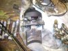
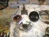
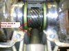
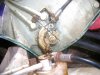
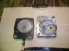
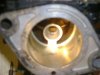
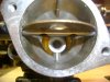
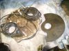
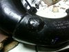
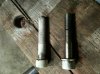
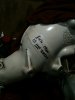
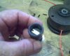
I'm attaching a picture of the post, out of the boat (it's in my hand) and the lanyard cap (with the metal part in contact with the ROM) and then, the two snapped together.
 

Attachments

  • DESS cap.jpg
    DESS cap.jpg
    116.6 KB · Views: 2,460
  • DESS post.jpg
    DESS post.jpg
    107.3 KB · Views: 2,061
  • complete.jpg
    complete.jpg
    130.2 KB · Views: 2,318
Last edited by a moderator:
New....

The following pictures are what a newly installed 787 should look like. Any comments or questions about parts you see that aren't listed, please send PM and I'll address it for you.
 

Attachments

  • Complete 787.JPG
    Complete 787.JPG
    43.8 KB · Views: 4,506
Last edited by a moderator:
Submerged 787...

This is what the 787, that was submerged for a year, looks like. I've already removed some of the parts and it's sitting upside down on it's cylinder heads. If you have questions, please feel free to PM me.
 

Attachments

  • Short Block.JPG
    Short Block.JPG
    62.6 KB · Views: 5,396
Last edited by a moderator:
Rave....

So many questions on the RAVE (rotax adjustable variable exhaust). Here is a pix of a complete unit with the dirty guillotine slide valve. You will notice on the right of the pix is the oil pump and to the upper right is the rotary shaft plate.
 

Attachments

  • Complete RAVE.JPG
    Complete RAVE.JPG
    639.8 KB · Views: 5,072
Expanded views....

Here are some views of the RAVE disassembled into the parts; slide (guillotine) valve, bellows, cap and spring and the foundation base. You'll notice to the right of the picture, the rotary shaft plate. Look closely on that plate and you'll see a brass nipple fitting. That's the oil injection nozzle that distributes the oil into the engine, behind the carbs.
 

Attachments

  • Rave exploded view.JPG
    Rave exploded view.JPG
    683.8 KB · Views: 3,675
Rave Cleaning....

Once a year, you should be removing the RAVEs to clean the carbon deposits from the slide valves. This is easily done with brake or carb cleaner. I use a small piece of copper that I've flattened to a "scrapper' type tool. The copper is softer material than that made of the RAVE, so, it shouldn't gouge and is great for scraping of the tough spots.

The most important part of the cleaning is the sides of the slide. And don't forget to clean the grooves of the cylinder head with that copper "scrapper". The carbon that will fall off into the engine while cleaning won't harm the engine. If you use a carb cleaner on those parts of the slide groove on the engine, I recommend that you let that cleaner completely evaporate, then pour about a coke bottle cap full of your two cylce oil into the cylinder (the carb cleaner will remove the cylinders oiling film).
 

Attachments

  • Clean Rave.JPG
    Clean Rave.JPG
    63.7 KB · Views: 3,574
Rotary shaft....

It seems we've been getting a lot of questions and some having problems with their rotary valve and shaft. So, I've got a pix I'd like to share.

The picture shows where the worm gear and crank come together. IF you look toward the bottom, where the lower red line is, that's the rotary shaft, where it couples the crank and leads out to your rotary degree valve plate. Notice the color of the gear, it's brass. This is designed to shear in the event of rotary failure so that damage to the crank either doesn't occure, or is minimal.

Notice the 2 green, round pieces on either side of the crank gear. Those are the seals we've all been talking about. When you find your engine is smoking really bad and won't stop, these seals are likely to blame. They seperate the oil bath from the pistons. Notice the muddy, blurr on each side, those are the cranks edge, to which the mag and pto piston are located. So here, you can see the proximity to the oil chamber.

BTW, this engine is upside down, that's why the rotary shaft looks like it comes out from under the crank. In your PWC/boat, it's actually located over the crank.
 

Attachments

  • Rotary Shaft Close up.JPG
    Rotary Shaft Close up.JPG
    41.7 KB · Views: 3,871
Lower engine....

Here is a picture of the lower end of the 787. The first thing you'll notice, it's upside down.

The next thing, look at the connecting rods at the crank. You'll see and be able to determine, how long this thing sat submerged in water. I got it a year after it went under and when I pulled the exhaust manifold, water poured out of it.

With this view, you'll be able to see how close the rotary shaft is to the other parts of the crankshaft. The small area between those two green pieces (rotary shaft seals) is filled with oil. Notice once again, this is a worm gear and needs constant lubrication at 7000 rpm. I've read post where members have either plugged these lines or some that bought the ski with them removed. Then they were wondering why the ski wasn't running. Here is a good view to help those understand the value of those oil lines to the rotary chamber at the bottom of the engine. You have one line to the chamber and one line that leads back to the tank, as a vent.

Some have posted about the smoke. If the ski sits up for any prolong period of time, some of the oil from that chamber will pass through to the combusion side. This is normal and occurs with age. If the smoke doesn't clear up after running for a short period, then the seals may be close to needing replacement. If your combustion chamber is hydrolocked with oil, then those seals are completly gone and will need a crank replacement.

Notice the balance shaft to the top of the pix. On the far right of the picture, you'll notice the seal at the counter weight. This is where you put your 30wt SAE motor oil. This is to lubricate that the two cog gears between the crank and the balance shaft. The balance shaft is the equivalent of the "harmonic balancer" of your cars engine. On the early models, this shaft is oiled, then sealed when built. There is no way to add oil unless you tear the engine apart. Newer models actually have a plug you can remove toward the back of the engine, near the PTO flywheel and oil may be added.

The biggest worry is from owners that find out about this oil in the shaft and think it's something they have to pour in and fill to the tip top. You don't. It only has 1 ounce in it. Also notice, the seal. The one in the pix is a little twisted from me splitting the casing, but that seal and the ones around the crank shaft, keep that oil from moving into other parts of the engine. Under normal circumstances, it shouldn't need to be maintained. If you do add oil, never fill it to the top. Filled to the top, when the engine runs and the heat builds, the oil will expand. So, in that expansion, you take a chance of blowing out the seal, losing the oil, then burning up the cog gears, causing total destruction.

Review the pix and the associtaed tags I put on it. That should help you understand the make up of the crank, connecting rods and balance shaft.
 

Attachments

  • Crankshaft and connecting rods.JPG
    Crankshaft and connecting rods.JPG
    67.9 KB · Views: 4,213
Cooling water...!

The cooling water flow has been, I think, largely mistaken on how it operates though the engine.

I'm going to explain and show the concept of cooling the engines of the 587, 657, 717, and 787, since they are all basically the same. The 951 is also, but with a few differences.

The cooling water enters the head cover from the pump when enough pressure is established (a "t" in the line to divert to the water regulator). This water enters the head cover at the bottom, rear connection. From there, if your looking at the attached picture, the water follows the blue path where it circulates around and over the top of the piston heads. Notice the red "0" rings in around the spark plug hole. This ring seals the head to the cover at the spark plugs. If your engine is leaking water out from around the spark plug, this is the likely reason.

There are a coule tiny (1/8") holes in that blue path, as the water crosses over to the tuned pipe (which you can barely see at each side of that bottom head plate, on the upper end on each side), which is there to allow water to fall into the water jacket for flooding, it is not part of the cooling process.

The water leaves the head cover from that outlet connetion on the forward end of the engine, going into the tuned pipe (water hose is normally only a few inches long).

Here, the water makes several revolutions around the pipe on it's way to the exhaust manifold (where the 4 bolts are connecting the manifold to the pipe) being preheated along the way, so cold water doesn't go into your engine, lessons the risk of thermal shock (don't know how many of you has poured a hot pot of tea into a glass pitcher, then add cold water! if you have, you get the picture). Where these 4 bolts are that connect the pipe and exhaust manifold, you'll see your "tell-tale" line. This line is at the highest point of the cooling system. It's main purpose is to expel all air out when the cooling system is being pressurized. When the air is out, the line will squirt water from it. This is a good sign that water flow has been established. The stream will go from weak to strong, depending on the rpm of the engine.

The water is then divided at the top of the manifold/tuned pipe into 4 sections (6 on the newer 787) as it makes it's way through the exhaust manifold into each cylinder head. There, the warm water flows around the cylinders outer casing where the heat transfer takes place. The combustion process of the piston generates a lot of heat, it's transferred to the water, then travels back up to the top of the head and cover plate.

Now, looking at the attached pix again, you'll notice the red lines, to signify hot water outlet. I've tried to mark in a pinkish/purple color, where the slots are in the head where that water is forced up from the bottom of the block and into the outlet side of the head casing. From there, the water is ejected from the boat. This is also where your temperature sensor is, on the outlet. If you look at the upper left hand corner of the pix, you can make it out, under the red line I used to show flow. Had I thought about it before I did the photoshop, I'd had drawn around it. :rofl:

To finish, look at the way the bolt pattern is set up. You will notice a "wall" between those two lines. That's what it is. A barrier wall to keep the cool water from the hot water. If you remove this cover, make sure it is clean before it goes back together. It's a machined surface, so it should not require any sealant (although I personally put a very thin film of blue RTV just for added security).

The only thing I can't show you, but will come in to edit, is this cover is torqued to the cylinders using an "0" ring in the bottom of that head cover to seal the combustion side from the water jacket side. The reason you here, "start the motor first, the water last and when shutting down, the water turned off first and the engine shut off last", is because the water pressure from your hose is capable of overcoming the "0" rings and dumping water into your pistons. So, always start the engine first before the water and turn the water off before the engine........always, no exceptions.
 

Attachments

  • Water flow.JPG
    Water flow.JPG
    126.7 KB · Views: 3,835
  • Cylinder head.JPG
    Cylinder head.JPG
    191.1 KB · Views: 2,241
Oil pump.

With some members looking for the instructions on how to check to see that their injection pump is still lined up after doing a carb rebuild, lets see if it's tru that a picture can tell a thousand words.

After you do your prelimanary set-up on the carbs, when you turn your idle stop screw in two full turns, it says to now, check the injection pump alignment.

After the carbs have had their final adjustment and you turn the idle stop screw in two turns, you'll want to set your oil pump. Looking through a mirror, I took this pix. You'll see a black line that runs through the center of the cam and shows the mark up where they need to be aligned......:cheers:

The pix I have uploaded, really doesn't show a good representation as to what your looking for.

It's already hard to see because you need a mirror but, you are looking to align your cam wheel, up even to the two little knobs I've outlined in red. If you look at your pump hard enough, you can also see, just below them (not in my pix), there is a round post with a slash mark across it, this is also an alignment mark as to where the cam wheel should be once your in alingment.

I hope this makes it a bit more simple...
 

Attachments

  • Oil pump alignment.jpg
    Oil pump alignment.jpg
    518 KB · Views: 2,352
  • Oil pump marks.jpg
    Oil pump marks.jpg
    79.6 KB · Views: 2,240
Last edited by a moderator:
The Mikuni BN carbs

I’m going to go over a little of the operation of the Mikuni SBN series carburetors, since the forum is filled with request on how to set the idle stop screw, how far out to turn the “low speed” screw, etc.

We all know that to adjust the low speed screw, we turn the screw in till we meet resistance, then out from 1 to 1 ¼ turns. But there have been many asking about setting the high speed screw. Well, my advice there was, “your screwed if someone removed the cap”. Well, I went through my other carb today and found that the high speed screw was missing it’s cap, so I decided to do a little test. I wanted to see where it was set. I gently tried to turn it in and it didn’t. So, when the manual says “0” on the high speed adjustment, that’s what it is. They give us the option of opening it up to ¼ turn for fine tuning.

If you don’t have the cap on your high speed screw, then gently turn it in till you meet resistance. Make sure you keep track of that setting. If it was like mine, it will be zero. If you turn this screw out, I’d still only turn it a very small amount at any one time. With a needle valve, small changes can be a big flow rate change.

The Mikuni draws fuel in from the gas tank by the engines pulse line. This pulse line drives a diaphragm type fuel pump. The fuel passes through a series of check valves. The fuel required for the variable speed of the engine, goes through a strainer before going on to the jets. The excess fuel is diverted through a restrictor, which acts like a fuel pressure regulator.

After the fuel passes through the strainer, it goes directly to the needle valve assembly, then to the fuel chamber. Fuel flow into the fuel chamber is controlled by the regulator diaphragm, arm spring, arm and the vent to the atmosphere. These components, along with the needle valve make up the regulator portion of the BN. The manual says the BN carbs are part carb and part regulator. The regulator portion controls fuel flow at slower speeds from idle to about ¼ throttle. The carburetor portion controls fuel from about ¼ throttle to WOT.

At idle, fuel is drawn through the low speed jet to the low speed outlet, via the low speed adjuster, and to the bypass holes. The low speed adjuster controls fuel flow for a smooth idle and initial throttle response. As the throttle valve is opened from the idle position, the bypass holes are increasingly exposed to the air flow. Their function is to help the carburetor “transition” from low speed to high speed operation. The size of the low speed jet directly affects fuel flow through the bypass holes for low speed performance. The other function affecting low speed performance is the regulator portion of the carb. The regulator portion can be tuned by changing the arm spring tension of the size of the needle valve or both.

When the carb is in transition to high speed, fuel is drawn through the check valve, and initially through the high speed jet. The function of the check valve is to prevent the low speed circuit from sucking in air through the high speed circuit at throttle openings of less that three eights. Fuel from the high speed jet passes through the inner venturi then into the engine. The high speed adjuster controls the maximum amount of fuel flow for full throttle performance from about ¾ of the throttles opening.

I have taken a series of pictures that may help you to identify parts to your carbs. I’ll try to list them as to what they are so you can make out what your looking at.

Picture 1 is a look at the Mikuni low speed screw, and the idle stop screw. You’ll notice I’ve already removed the throttle plate. The fuel chamber is at the low speed screw and to the left. The venturi of the carb is the rounded outline, from where you see the hole of the throttle plate, to the top of the carb (I’ll talk about this later.).

Picture 2 is the needle valve of the “low speed” screw. The needle of the screw is pointing directly at the low speed fuels entrance into the carb. When you open the “low speed” screw, more fuel passes through that hole. Close it, vice versa.

Picture 3 is of the Pump cover with the clear pump diaphragm still attached. The pump body assembly is to the right. You can see the check valves which control the fuel flow easily.

Picture 4 is the small filter inside the carb that we all talk about. I wish I had held my finger next to it so you could get an idea of the size. About the thickness of a pencil and about 3/4” long.

Picture 5 is dark because I tried to get a good shot of the restrictor hole that has been referred to. You can see it in the bottom of the inlet hole. It can’t be any larger than 1/64” in diameter.

Picture 6 shows the choke plate, the outer and inner venturi. The inner venturi is where the high speed jet is. When you adjust the “high speed” screw, the fuel being able to pass through that venturi is increased and/or decreased. It’s a bit blurry because of the angle and how close I had to get to it, but if you look in the center, on the bottom, you’ll see the “hole” where the fuel is pulled through the venture into the engine.

Picture 7 is a better view, looking through the carb at the high speed venturi. Notice the change in carbs body size. That part of the carb is called the outer venturi. The venturi effect is necessary for the carburetor to work. It uses that kinetic energy created to pull that fuel in through the high speed gas jet, which is the inner venturi, and deliver it to the cylinders for combustion.


From Wikipedia: The Venturi effect is the drop in fluid pressure that results when an incompressible fluid flows through a constricted section of pipe. The Venturi effect may be derived from a combination of Bernoulli's principle and the equation of continuity. The fluid velocity must increase through the constriction to satisfy the equation of continuity, while its pressure must decrease due to conservation of energy: the gain in kinetic energy is supplied by a drop in pressure or a pressure gradient force.

In our case of the carb, the kinetic energy generated by the venturi effect is the fuel being sucked from the inner venturi (high speed jet). There is no fuel pump driving pressure behind it, only the pumps pressure from the impulse line to deliver it to the fuel chamber.
 

Attachments

  • Pix 1.jpg
    Pix 1.jpg
    130.5 KB · Views: 2,463
  • Pix 2.jpg
    Pix 2.jpg
    132.4 KB · Views: 1,959
  • Pix 3.jpg
    Pix 3.jpg
    132.5 KB · Views: 1,819
  • Pix 4.jpg
    Pix 4.jpg
    133.6 KB · Views: 1,648
  • Pix 5.jpg
    Pix 5.jpg
    128.1 KB · Views: 1,438
  • Pix 6.jpg
    Pix 6.jpg
    60.2 KB · Views: 1,417
  • Pix 7.jpg
    Pix 7.jpg
    127.9 KB · Views: 1,552
Last edited by a moderator:
Rotary installation...

The Rotary Valve controls the opening and closing of the inlet ports.

The timing of the rotary valve on the 787cc engine is a 159 degree valve, part number 290 924 502. This is the same valve used in one model of the 717cc. Some models of the 717cc use a 132 degree valve, part number 290 924 504.

Timing the rotary valve is a pretty simple process but to some, it seems intimidating. The following procedure will describe how to time the 787 without special tools. If you take it to a shop, the mechanic will probably use a degree wheel and a TDC (top dead center) gage. I use my daughters protractor from her math folder and a pencil to help me find top dead center.

The first step in timing the rotary is to find TDC on the MAG piston. You should already have the battery disconnected, if not, do so. Take out your spark plugs for ease of turning the shaft over by hand. The shaft guard on the back of the PTO should also have been removed. Put your pencil ( unsharpened) in the MAG (front cylinder) and using your left hand to turn the shaft counter clockwise and your right hand to steady the pencil, turn the engine till the pencil rises to the top of the stroke (piston all the way up at it's furthest point of travel). When your at the top, move the shaft back and forth and watch the pencil. You want to stop the shaft when it's directly in the middle of the upper part of the stroke.

While performing this procedure, it is very important that the crankshaft not turn. If you turn the crank, the procedure has to start over again.

First, we will find and scribe the open setting. Using the degree wheel, or protractor, lay it against the rotary shaft, with the 360 degree mark orientated right at the bottom edge of the MAG cylinders inlet port. Then, find the 146.5, plus or minus 5 degrees, on the degree wheel. Scribe a mark on the side of the casing.

Second, we will find and scribe the close setting. Using the degree wheel, or protractor, lay it against the rotary shaft, with the 360 degree mark orientated right at the upper edge of the MAG cylinders inlet port. Then, find the 64 degree, plus or minus 5 degrees, on the degree wheel. Scribe a mark on the side of the casing.

Third, position the rotary valve on the shaft splines to have the edges as close as possible to the marks you scribed on the casing. The rotary valve is asymmetrical so if it doesn't line up close enough to the marks while sliding it on the splines, try flipping it over and trying from the opposite side.

Lastly, apply a little of your 2-cycle oil on the rotary before assembling the cover. The four bolts should be torqued in a criss cross pattern until you reach 15 foot pounds.

If your engine backfires on a regular basis, you could have an improper setting of the rotary or the brass worm gear in the chamber has stripped the woodruff key.

The attached picture is of the rotary cover which shows a good view of the brass oil injectors, the "0" ring and the 159 degree valve
 

Attachments

  • 080321_134715.jpg
    080321_134715.jpg
    158.2 KB · Views: 1,765
  • Rotary cover.JPG
    Rotary cover.JPG
    625.5 KB · Views: 1,651
Magneto...

The purpose of the battery is to have an electrical charge with enough cold cranking amps to spin the motor over with the high compression of a 2-cycle engine, and make the combustion process start. It is also the supplier of current to the MPEM (multipurpose electronic module) and all accessories.
The purpose of the magneto is to keep your battery at a full state of charge and is the primary source of engergy to your electrical system via the battery. The magneto is designed to use a magnetic field to create an alternating current of electricity.
In the 587 and 717 engines, the magneto has a three pole coil with a capacity of 160 watts of current.
The 787 engine has a “Y” wound stator on 18 poles and creates 180 watts.
Because the Rotax engine runs on 12 volts direct current, there is a regulator/rectifier that is built in to the system to convert and maintain. The rectifier converts the AC power into DC power. The regulator maintains the charge between 14.5 to 14.8 volts.
The charging system is protected by a 15 amp fuse (on XP models, there are 2). If you find the battery in a constant state of discharge, check this (these) fuses. If they are blown, never replace with a higher fuse as damage to the rectifier/regulator may occur.
CURRENT TEST
To perforum a current test, start the engine. Use an inductive ammeter on the positive cable of the battery. Bring engine up to about 5500 rpm. Depending on the batteries charge, your current reading should be 4 amps for the 717 and 5 amps for the 787.
The most easiest and most used test is with a multi test meter. Set the meter to 20 VDC and read the battery. It should have about 12 vdc stored in it. Then, start the motor. Now, test the battery while the motor is running. Your reading should be about 14 to 14.5 vdc. If the reading is greater than 15 vdc, then you probably have a defective regulator/rectifier.
The best way to ensure your battery is receiving a charge is maintenance. I’ve come across people with dead batteries and when I go to help, the first thing I notice is the battery isn’t strapped down. Then, I notice the buildup of battery corrosion (white powdery stuff) all over the terminals. Then, there is the occasional loose ground. When this is occuring, the ski is normally starting off the battery but under those conditions, the magneto isn’t capable of restoring the power back to the battery. So, you use it several times through the day, it gets weaker and weaker, till it can no longer provide the cranking amps needed to start the motor.
In the picture, you’ll see a magneto that has been removed from the 787cc engine. It shows the “Y” wound stator with 18 poles (easily visible, count them) and the trigger coil. Then, you’ll notice to the right side of the stator, the magneto flywheel. See that small piece of metal on the outside? That’s what breaks the contact on the trigger coil, sending the signal to the coil that it’s ready to spark the plugs.
Mechanics know, that in most applications, a coil or coils, send spark to each plug at the designated time of ignition. With a few applications of the single coil set-up, in this case, the 787cc, the timing is 180 degrees apart and is the reason why the coil fires both plugs at the same time. Though only one cylinder is receiving the power from combustion.

Credits to the Shop manual for the 1996, 587, 717 and 787 cc Rotax engines
Credit to robin savell lloyd for the debate on the proper sequence in spark from the 787 ignition system.
 

Attachments

  • Magneto.JPG
    Magneto.JPG
    65.7 KB · Views: 1,930
December of 2009!

Well, here it is, December 2009 and I've had to pull the 787cc of my boat. The engine all of you have been looking at is from a 1996 787cc that had sunk. I am in the process of rebuilding that motor but this one, from my family boat, the 1997 Challenger, failed on me on July 4th of this past year.

The boat ran great while just cruising around, pulling the tubes with the kids but when I went to wide open throttle, it would run for about 5 minutes, then slow down and die.

It seems that something was getting into the combustion chamber that was not burnable. You know, something beside gas and oil.

Well, it took me 2 and a half hours to pull the motor today and I took a few pix for all to look at. This engine is the original engine, it's also still maintaing roughly 140 lbs of compression but from all the salt water use from the previous owner, it's starting to look kinda worn.

I have a couple pix of the engine bay, just after pulling the motor. I had a bucket under the oil lines when I disconnected them but, the bucket filled up rather quickly and then, before getting another, spilled a bit in the floor.

The second pix is of a blurry shot looking from the front of the motor. I pulled the entire motor by disconnecting all carb linkage, then taking all oil lines and cutting under the bottom of the tank and wrapping around the motor.

The 4th pix is of the side view at the rotary valve. I had just finished sparying white lithium grease for preservation.

The 5th pix is one of what I think, might be a part cause to my problem. When I looked into the exhaust (you could not see it even if I zoomed in with the camera), there was water droplets inside the pipe (now, not from breaking the seal I dont' think, because I had blown all the water out before working on it).

What I think happened is, with that bolt being broken, when the pump pressure built up with the increase of horespower, it allowed water to enter the combustion chamber and mix with the fuel/oil to stop combustion.

Anyway, I'm going to air test the motor first, to see what I can find out. Then, because it is the original engine, I'm going to open it up and do an inspection. CHecking clearances and so forth.

Balance Shaft oil... With the debate of the balance shaft, I'm also going to gently seperate the bottom end so I can inspect the shaft oil. This motor is over 10 years old, never been rebuilt. So, I'll be curious as to the condition of the oil (if it has some). When these motors are in position, the CB shaft is in a downward position, where the oil can be stored. This engine also has no plug to maintain this oil.............so, come back and see if I've updated. I'll be back and forth as I take parts off and let all you guys know whats going on...........:cheers:
 

Attachments

  • 1pix.jpg
    1pix.jpg
    623.2 KB · Views: 1,765
  • 2pix.jpg
    2pix.jpg
    861.1 KB · Views: 1,604
  • 3pix.jpg
    3pix.jpg
    499.1 KB · Views: 1,649
  • 4pix.jpg
    4pix.jpg
    560.1 KB · Views: 1,675
  • 5pix.jpg
    5pix.jpg
    384.3 KB · Views: 1,535
Plugged fittings....

Today, after pulling the motor for the Challenger, I noticed a few things I'd like to pass on.

Winterizing? A lot of the time, you'll hear someone say to just blow the water out, it'll be fine. I'm also guilty of this, thinking that I've expelled all the water. In the exhaust system, the resonator and muffler expansion tank is set up so that all water can not be removed. Heck, I even took it off and shook it upside down and couldn't get all the water out. So, mixing a bit of antifreeze for this area, even from the south, is something we should all do.

One more thing. In the back of the exhaust, at the muffler is where you have a calibrated fitting for your cylinder heads to drain. I found mine was completly stopped up. Therefore, my cylinders were not being drained, which if there was a quick snap, freeze, it could cracked one or both my cylinder walls.

So, for those living up north, I think I would make sure this line is not blocked.:cheers:
 
McGyver fix...?

A few years back, my tuned pipe began leaking at the water side of the pre-heater.

I've seen several members have this same problem. We've actually had a debate about it. Which way was the best way. Well, of course, to clean all the aluminum oxide and salt cholrides from the problem area and weld it, is by far the most perfect way of doing this.

But, as some may remember, I elected to try the JB weld, that comes in a tootsie roll type stick. I did a throuogh cleaning job, making sure to use my dremel to get all the bad material out of the area. I mixed the putty, used a piece of stainless screen to put over the hole and applied the JB weld.

I choose this direction for the most part, because the fluids moving through were not under a large amount of pressure from the jet pump. After repairs, I painted it black.

UPDATE: April 28, 2011 After a couple years, this fix is still holding and no water is leaking at the repaired plugs.

I'd just like to say, after 3 seasons, the JB weld is still holding. Not is it just holding but the integrity seems to be as strong as if it were welded. When removing the engine from the boat today, I took a second to check the system repairs out and was surprised, I couldn't drive my pick through it.

Here are a couple attached pix. The small up-raised bumps are the areas of repair. I had about 12 holes in both the top and bottom. One hole was about 3/8" once it was grinded out smooth.......:cheers:
 

Attachments

  • 6pix.jpg
    6pix.jpg
    417.3 KB · Views: 1,229
  • 7pix.jpg
    7pix.jpg
    359.7 KB · Views: 1,060
Last edited by a moderator:
Replies and Questions to the 787cc thread?....

For the past several years, I"ve kept this thread locked so as not to clutter the information with a host of questions and statments. I have had interested members ask that they be allowed to comment or ask a question as to something relevant to their problem.

Because of the amount of info in the thread and constantly growing, I would still like to keep it locked. But, I'm going to make a thread where members can post a question or comment so I may be able to respond to them. Whether its just a comment, a statement that is debatable or just someone looking to clarify a problem spot.

Please, feel free to post in this new thread, any questions you might have about this thread on the 787, make sure you note the post number so I can refer to it in answering your query......:cheers:
 
1997 Challenger...

Well, I got the motor in the shop and broke it down today. I thought I was just going to replace gaskets and be able to put it back together. I've made a video that I hope to put into the forum, for all to watch. I've had a problem with Windows 7 crashing all my Ulead Video editing studio software, so I've been restoring the equipment (dumped Windows 7). So, I have several vids that I hope to soon get posted for all to see.

My problems...... It doesn't look like a simple gasket replacment. I may replace the motor. I"ve thought about doing an upper end but for the moment, don't know that conditions of the bearings. I"ll be splitting the casing and doing some measurements along with shaft deflection to see what kind of condition the bearing and crank is in.

With the motor being over 12 years old, the original motor, I might as well do a complete engine. I would hate to do an upper end, just to loose a bearing later.

I've attached pix of both pistons. They are scared pretty bad, like something got into them. But, I know that did not happen. It may be caused from a lack of oiling. It could as well happened before I bought the boat from the original owner almost 4 years ago. But, I thought I'd put the pix in for all to see.

Oh, the measurements of the MAG piston ranged from 81.42 upwards to 81.86. The cylinder measured 81.74 to 81.80. The PTO ranged from 81.61 upwards to 81.74 and the cylinder measured 81.57 to 81.68. Of course, 82.00 is standard size. I don't see me being able to bore this out to 82.00 because of the terrible wear.:(
 

Attachments

  • MAG piston.jpg
    MAG piston.jpg
    417.5 KB · Views: 1,377
  • PTO piston.jpg
    PTO piston.jpg
    460.5 KB · Views: 1,232
Update:... I'm in the middle of a rebuild to my 1997 Challenger. I will be adding some pix to this thread, that are specific to the ring gap and ring groove measurements. This is a real basic test to help you decide if you need to replace your pistons or reuse them. Check back on the thread later in the week....
 
It's been a while since working on the 787cc for the boat, but I've been coming along, little at a time.

I wish I had taken more pix, but for some reason, with limited time, I haven't keep up with it. I think, pix of doing the required tests to see if your cylinders and pistons are good, would have been important to the novice mechanic. But, I have another motor that I can use to show how to check them.

What I'm wanting to show right now is the importance of making sure your threads are clean before doing any torque procedures. All of us know that the white powdery substance (aluminum oxide) is a pain when we're trying to take something apart, especially if it's been on for several years. Trying to set torque with dirty threads will cause an improper torque and could cause you to strip your threads out. So, make sure you check them.

Here, I'm cleaning up and installing the exhaust manifold gasket. You'll see the attached pix of me using a tap (M10 for exhaust bolts) to clean out the bolt hole cavity. If you don't have taps, you can use the bolts themselves by applying a little anti-seize. But, when you finish, it's a good idea to try and remove as much of the anti-seize as possible because that too might give you a false reading. You can spray carb cleaner into the holes to clean out. The bolts need to be wire brused clean. In the pix, you'll see one bolt with the white powder stuff and the other has been brushed clean.
If your motor is old, like the 90's model 2 strokes, and hasn't been taken apart in a while, chances are the lock washers are flattened out. You might want to replace them also. While doing any work on the matting surface of the manifold, make sure you stuff shop rags into the exhaust ports to keep foreign debris out of the motor.

Lastly, it's hard to finish a complete rebuild in one day, or a few hours, depending on how much time you have to do the work. I find it best to take a piece of masking tape and write on it with a sharpie, where I left off. For instance, in this post, I stopped at the torque procedure. That way, when I come back to work on it, I won't move onto something else without doing the torque on the exhaust manifold.

Next, doing an air test.......
 

Attachments

  • Exh Man Bolts.jpg
    Exh Man Bolts.jpg
    410.7 KB · Views: 686
  • Tap out.jpg
    Tap out.jpg
    363.5 KB · Views: 709
  • Lable Torques.JPG
    Lable Torques.JPG
    246.3 KB · Views: 706
Status
Not open for further replies.
Back
Top