96 GTX rectifier diode test

Note: This site contains eBay affiliate links for which SeaDooForum.com may be compensated
Status
Not open for further replies.

Mohannad57

New Member
Hi

I'm new to troubleshooting a Seadoo, especially the electrical parts of it, but I came to point that my battery is not charging as I tested the voltage at the battery while pushing the RPM to 4500/5000 and my battery voltage doesn't move from 12.4sh.
So I consulted a mechanic and they said rectifier/regular(RR) could be bad and or MPEM,
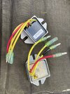
So I started with buying new RR, and wanted to test the diodes on it using a multimeter and compare with the old one. But with booth RRs I'm getting almost no reading or very odd reading of .001, and they both give same reading. So are they both bad, or I'm not testing the diodes correctly.
Looked at many videos to test the RR, but no luck.
here is a picture of my RR and please help me test.
The seadoo I have is a 96 GTX 787.

Please help.
and thank you in advance.
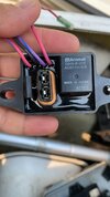
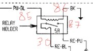
 

Attachments

  • image.jpg
    image.jpg
    547.9 KB · Views: 14
  • image.jpg
    image.jpg
    240.6 KB · Views: 12
I have honestly never tested one.
You seem to either have a good one or a bad one.
If you unplug the red wire from the regulator and the ski runs good it is bad.
If you check battery voltage at idle and it is below 12V it is bad.
If you rev up the engine to 4,500 rpm and you are not at 13V-14V it is bad.
 
Thanks for the response, but I just want to clarify If I unplug the red wire, should the seadoo not start at all, or it could start but it will die eventually as the battery will be drained and never charged.
mad for mine if I unplug the red it starts but don't know for how long as I never tested for long time. But if the RR ground is not connected the seadoo never starts that I noticed.
 
It should start and run fine, the battery just won't be charging. Your electrical system will just be running off battery power.
 
Thank you,
One more thing I should add that the RR red is connected to relay that has a 5amp fuse that keep blowing off, which is why I figured) the guy had it before replaced it with a 10 amp. That would caused some damage to the mpem, wouldn't it?
 
I had one go bad on my SPI and blew the diode on MPEM. I didn't know what happened but when troubleshooting I had a short on two of the wires on this rectifier in the picture. If I remember correctly they said these cannot be tested with any degree of certainity.

There is a test you can do on the coil to make sure you're getting the proper voltage to the rectifer. I just test voltage at the battery. If the battery is in decent shape you'll see the voltage increase. Good Luck.
 
Thank you,
One more thing I should add that the RR red is connected to relay that has a 5amp fuse that keep blowing off, which is why I figured) the guy had it before replaced it with a 10 amp. That would caused some damage to the mpem, wouldn't it?
That 5 amp fuse protects your diode and the computer.
 
I managed to get reading at the battery up to 14 so I figured it's charging now, but it keeps blowing up the 5 amp fuse on the relay.
So I put it back to 10, and it seems there are but I'm afraid that will destroy the MPEM?
so how can I keep the 5 and manage not to blow it up. What part do I need to replace, or test?
 
Do you mean the diodes on the rectifier or the MPEM?
The 5 amp fuse protects the MPEM. If you connect the battery incorrectly, the 5amp fuse will blow. That doesn't guarantee the MPEM is saved but if that fuse isn't there It will likely damage the MPEM. The rectifier on my 96 SPI had an internal problem and shorted out and fried my MPEM and blew the 5amp fuse.
 
If you are blowing the 5 amp fuse something is trying to backfeed. Positive Voltage is likely getting to the ground wire and coming back in or your MPEM is bad. If this is a 1996 GTX in the manual there are measurements you take on the MPEM and the Plug for the CDI to determine their health. I had a lot of trouble identifying any problems. I'd check the wiring.

Is that relay to which you are referring the "Holder Relay?"
 
The relay is the one connecting the rectifier to the MBEM through the 5amp fuse.

what could cause the 5amp to blow?
Can I try to connect the rectifier directly to a battery (an external one) and see if it charges?
 
Pictures would help. The only relay I remember in the gray box is the Holder Relay and it is a small black box shape with a coild and a fuse. It is a power source for the rear electrical box and if it doesn't work, the ski doesn't start.
 
Pictures would help. The only relay I remember in the gray box is the Holder Relay and it is a small black box shape with a coild and a fuse. It is a power source for the rear electrical box and if it doesn't work, the ski doesn't start.
Here are couple of pictures of the it.
 

Attachments

  • 306868F5-D8F8-40BD-BAA6-99D219F7C52E.jpeg
    306868F5-D8F8-40BD-BAA6-99D219F7C52E.jpeg
    173 KB · Views: 7
  • 2A057679-DE5C-40CB-9115-87F0C9F1662B.jpeg
    2A057679-DE5C-40CB-9115-87F0C9F1662B.jpeg
    44 KB · Views: 9
That is the holder relay. It's easy to test but if you connect the wires incorrectly you'll burn it up really quick. :) I took it apart to see how it worked. Those coil wires are really really small. Is this what is blowing the 5 amp fuse or the the fuse in this relay blowing? That narrows down where you voltage is coming from.
 
That is the holder relay. It's easy to test but if you connect the wires incorrectly you'll burn it up really quick. :) I took it apart to see how it worked. Those coil wires are really really small. Is this what is blowing the 5 amp fuse or the the fuse in this relay blowing? That narrows down where you voltage is coming from.

The fuse on this relay is blowing, I don't think this is what causing it to blow though.
as I tested this relay and it is function as it supposed to be.

But I just realized something right now as I'm looking at the electrical diagram right now, in my seadoo the voltage regulator/rectifier red wire is connected to this relay directly, however in the diagram it should not be. The red wire should go to the mpem and from the Mpem to the relay, see image.
It seems that someone had been missing with this box badly...
I'll go by the diagram and test it today and let you know.
 

Attachments

  • C9DED40C-EB35-4CF3-B99E-F601FE978EA0.jpeg
    C9DED40C-EB35-4CF3-B99E-F601FE978EA0.jpeg
    357.4 KB · Views: 7
I'll open a gray box this afternoon and have a look. Maybe take a picture. :) Your current wiring may well be the reason the fuse is blowing. Happy Hunting !
 
Status
Not open for further replies.
Back
Top