Hello everyone, after extensive research on the VTS system for my 95 Sea Doo XP I come to the concussion I needed to build my own system to control it because I was not impressed with the track record of the OEM system and did not want to buy a new one to fail, and I wanted to have limit switches to control the max travel something aftermarket modifications did not have as far as I could find until now.
I was and am not overly concerned with the gauge working, I left that part of the VTS system intact with my modifications even though I have at least one dead switch with the OEM setup.
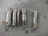
I found in my research that you can buy a shower valve wrench set at the hardware store that will remove the VTS box, I slipped a few together end for end to get the length I needed.
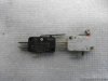
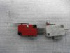
Then I disassembled the box and picked up a couple of lever/roller micro switches at my local electric motor repair. I wanted to use two of the lever type but all they had was one so I made the roller type work for one of them. However the lever would have been easier because you can put a slight bend in the levers to limit travel
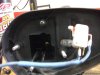
Then I did some careful measuring with some digital calipers and drilled some holes to mount the lower limit switch taped the holes in the plastic for the studs, trimmed the screws down to length, and added some spacer washers.
I made up some connections on the limit switch heat shrink the wires for rigidity so they would stay in place and used some small plastic clamps to hold the wiring up in the corner out of the way.
Then I made myself up an aluminum mounting bracket for the upper limit switch, that was a trick but I got it done, for thoughts that don’t know to bend aluminum multiple times without braking it heat it up with a torch, quench it in cold water, then bend it.
Quenching hot aluminum in cold water will take the work hardening out so that it can be bent over and over without braking it. The bracket was made using a map gas torch, cold water, hack saw, vice, pipe and a hammer to get the curve, a 4-40 tap for the treaded holes, (there is an extra set of holes in this bracket for the micro switch I did not use), file and a bench grinder.
And for the wiring I used a 451M directed electronics door lock relay setup, I have read many claims that this relay is 40 amps and that it is solid state, that is simply not true the relays are 15 amp relays as printed on them when you pop the cover apart, and they are not solid state, they have moving parts that’s why they make noise when you activate them. After disassembly of the relays I used some black silicone (the right stuff) as potting filling the housing up completely pushing the relays in and siliconing the back side to keep all water out of the relays, temporarily holding the cover on with black tape.
I cut open the wire sheath just as it left the VTS box, cut and removed all but the two brown gauge sending wires I left them alone, but remove the rest to use in my control wiring. Drilled a 3/8 hole in the back of the box for a ¼ grommet to run wiring though and made most of my connections on the outside of the box using heat shrink type butt connectors staggering them to reduce bulk and retain flexibility of the wiring then I picked up a roll of heat shrink to bundle the new wiring together so it would resemble the factory wining.
I did manage to get the relays and wiring all in the factory VTS box even though it was a really tight fit, I had to trim some on the inside lip of the cover to get it back on
I also drilled a couple of 1/8 holes in the bottom of the housing to allow any water to escape that gets in
Before all this retrofit moods I was using a simply built manual trim handle made by removing most of the motor and tack welding a handle to what was left it was also very handy in mocking up the limit switches
This was a very time consuming project but I thought I would share it because maybe someone else might use or enjoy it
Thanks Hoppy
more pics to come
I was and am not overly concerned with the gauge working, I left that part of the VTS system intact with my modifications even though I have at least one dead switch with the OEM setup.
I found in my research that you can buy a shower valve wrench set at the hardware store that will remove the VTS box, I slipped a few together end for end to get the length I needed.
Then I disassembled the box and picked up a couple of lever/roller micro switches at my local electric motor repair. I wanted to use two of the lever type but all they had was one so I made the roller type work for one of them. However the lever would have been easier because you can put a slight bend in the levers to limit travel
Then I did some careful measuring with some digital calipers and drilled some holes to mount the lower limit switch taped the holes in the plastic for the studs, trimmed the screws down to length, and added some spacer washers.
I made up some connections on the limit switch heat shrink the wires for rigidity so they would stay in place and used some small plastic clamps to hold the wiring up in the corner out of the way.
Then I made myself up an aluminum mounting bracket for the upper limit switch, that was a trick but I got it done, for thoughts that don’t know to bend aluminum multiple times without braking it heat it up with a torch, quench it in cold water, then bend it.
Quenching hot aluminum in cold water will take the work hardening out so that it can be bent over and over without braking it. The bracket was made using a map gas torch, cold water, hack saw, vice, pipe and a hammer to get the curve, a 4-40 tap for the treaded holes, (there is an extra set of holes in this bracket for the micro switch I did not use), file and a bench grinder.
And for the wiring I used a 451M directed electronics door lock relay setup, I have read many claims that this relay is 40 amps and that it is solid state, that is simply not true the relays are 15 amp relays as printed on them when you pop the cover apart, and they are not solid state, they have moving parts that’s why they make noise when you activate them. After disassembly of the relays I used some black silicone (the right stuff) as potting filling the housing up completely pushing the relays in and siliconing the back side to keep all water out of the relays, temporarily holding the cover on with black tape.
I cut open the wire sheath just as it left the VTS box, cut and removed all but the two brown gauge sending wires I left them alone, but remove the rest to use in my control wiring. Drilled a 3/8 hole in the back of the box for a ¼ grommet to run wiring though and made most of my connections on the outside of the box using heat shrink type butt connectors staggering them to reduce bulk and retain flexibility of the wiring then I picked up a roll of heat shrink to bundle the new wiring together so it would resemble the factory wining.
I did manage to get the relays and wiring all in the factory VTS box even though it was a really tight fit, I had to trim some on the inside lip of the cover to get it back on
I also drilled a couple of 1/8 holes in the bottom of the housing to allow any water to escape that gets in
Before all this retrofit moods I was using a simply built manual trim handle made by removing most of the motor and tack welding a handle to what was left it was also very handy in mocking up the limit switches
This was a very time consuming project but I thought I would share it because maybe someone else might use or enjoy it
Thanks Hoppy
more pics to come