stefano_62
New Member
This procedure shows how to repair the electronics components of the trim without having to replace the whole system.
They exist on the market some repair kits, very easy to intsall but consist of two simple relays inserted in a box. On this forum I saw the relay connection scheme for this simple and unexpensive solution. The cost for DIY is a few dollars. The big problem is that with relais only the trim end of course is not managed, with consequent current overloading both the engine, mechanics (in plastic) but above all for the Mpem.
Those who decide for this solution must be able to never use to the max or min trim position (end of course).
If you want to engage in a repair that will make it back as new, you can follow this procedure. It is not very difficult but it engages a long time.
I don't take any responsibility for damage than for inexperience or errors you could do to your system.
Seadoo Trim repair rebuild:
NOTE: ONLY FOR EXPERT !!!
Identify the correct trim part list number:

Disassemble all the mechanics and clean it very well with good degreaser


Note: location of the sensor magnet


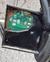
Crack in the original silicone sealant

.....continue.....
They exist on the market some repair kits, very easy to intsall but consist of two simple relays inserted in a box. On this forum I saw the relay connection scheme for this simple and unexpensive solution. The cost for DIY is a few dollars. The big problem is that with relais only the trim end of course is not managed, with consequent current overloading both the engine, mechanics (in plastic) but above all for the Mpem.
Those who decide for this solution must be able to never use to the max or min trim position (end of course).
If you want to engage in a repair that will make it back as new, you can follow this procedure. It is not very difficult but it engages a long time.
I don't take any responsibility for damage than for inexperience or errors you could do to your system.
Seadoo Trim repair rebuild:
NOTE: ONLY FOR EXPERT !!!
Identify the correct trim part list number:
Disassemble all the mechanics and clean it very well with good degreaser
Note: location of the sensor magnet
Crack in the original silicone sealant
.....continue.....
Last edited: