• This site contains eBay affiliate links for which Sea-Doo Forum may be compensated.

Is 4tec exhaust water injected?

Status
Not open for further replies.
What if....

What if I attach a U joint to the bottom of the JPipe, and have it take the flow up, above the WL to a cylindrical style muffler, then have it dip back down to exit via the outlet. That way, if water were to come surge back in, it'd have to go up, expand in the muffler, fill that, go back down, and back up before it can go into the manifold?

With this setup, I think I'd have to keep the exhaust pipe at or below the highest point of the JPipe, but still above the WL (when not on plane).
 
Yes, that's the correct way to think of this. Sounds like the factory setup had at least a couple of high spots above the water line to prevent back surging an then a container in low spots (waterbox) that provided a temporary place for cooling water moving through to collect when the motor is shut down. Ultimate goal is avoiding water backing up into the cylinder exhaust ports, this is the water necessary to keep the exhaust system components from overheating. This water would normally be pushed out by/with the exhaust gas pressure under normal conditions.

For a simple example in an open bilge with over the transom water cooled header, there's a small 1/8" hole drilled at the low spot below the exhaust port (the header tube takes an immediate turn downward from the exhaust port) where cooling water is injected, to act as a drain. Immediately after the motor is shut down some of the water remaining inside the header collector runs back down to this low spot and drains from the hole.

I'll try to find a drawing, even though it's not exactly the same except it serves the same function (to prevent water from entering exhaust port of the head).
 
I should also mention, avoid going too large on the exhaust pipe diameter. The diameter of pipe determines the velocity of exhaust gasses and if too slow the water will be more prone to backing up and not clearing out (water reversion can become problematic).
 
NOTED! Seadoo uses 2.5" diameter, but the Centek sizing chart suggests a 3.5" muffler. I called them and they asked for pics to better assit me, but did mention that with BRP motors, they usually tend to match the inlet/outlet diameters to the stock system without problems.
 
What if....

What if I attach a U joint to the bottom of the JPipe, and have it take the flow up, above the WL to a cylindrical style muffler, then have it dip back down to exit via the outlet. That way, if water were to come surge back in, it'd have to go up, expand in the muffler, fill that, go back down, and back up before it can go into the manifold?

With this setup, I think I'd have to keep the exhaust pipe at or below the highest point of the JPipe, but still above the WL (when not on plane).

That's basically what happens in an oem configuration. down from the J into the wb then back up high over the tunnel and on to the resonator at the same level as the outlet.

Even in a shorty or aftermarket wb....exhaust goes up out of it before back down to the exit.
 
What if I attach a U joint to the bottom of the JPipe, and have it take the flow up, above the WL to a cylindrical style muffler, then have it dip back down to exit via the outlet. That way, if water were to come surge back in, it'd have to go up, expand in the muffler, fill that, go back down, and back up before it can go into the manifold?

With this setup, I think I'd have to keep the exhaust pipe at or below the highest point of the JPipe, but still above the WL (when not on plane).

For this specifically, I think the JPipe should go directly straight down to the waterbox (a large box that can hold some water but clears out as exhaust passes through, outlet of box is at bottom of box), avoid any chance of long runs from the exhaust manifold which might allow some water to run back into the exhaust manifold and from the water collection box then run up above the water line again, before exiting the transom.

This would provide two high spots, as p-traps and one is the JPipe, to discourage water from running backwards into the exhaust ports, and the 2nd is to discourage seawater from running from the lake and flooding the waterbox.

I think you can closely duplicate the factory exhaust including the waterbox, maybe you have to modify the waterbox slightly due to reorientation, the waterbox outlet must be low in the waterbox so the waterbox doesn't fill with water, only a small volume of water remains in the waterbox while the engine is running, the remainder of the water is carried out of the WB outlet along with the exhaust, up past the 2nd high spot then gravity can do the rest.

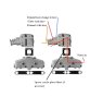
Maybe this is what you're thinking:

You could attach the muffler at the JPipe almost vertical, and with the outlet of the muffler pointing down, allowing the muffler to perform the same function as the waterbox (a place of volume for water to collect, instead of running backward into the exhaust manifold), then run a rubber/plastic pipe back up to above the waterline then from there back down through the normal exit.

In this case it's functionally the same aside from the location of sound deadening, the exhaust flow should keep the muffler from filling with water.

Anyway, I think you're on the right track.
 
For downward sections, it's probablt okay to have a larger diameter, if that's how the piping sizes work out. just trying to keep water from moving in the wrong direction (under all conditions).
 
"What if I attach a U joint to the bottom of the JPipe, and have it take the flow up,"

This is the part where it sounds like it should go directly down, in the same or similar orientation as the JPipe, the purpose of the JPipe configuration is to keep water from moving backward.
 
Yea, the problem I'm running into, is unless I further modify the internal hull dynamics, I can't fit much of a muffler under where the J-pipe terminates. I don't want to weaken the hull any, as I believe that the inner hull lining acts as stringers and increases structural integrity. This boat gets beat up pretty good on a choppy day. I wouldn't want to crack it going across the chop.
 
Agree, you should avoid cutting out structural components, that's as important as making sure water can't flow backward into the exhaust ports of the head. As long as the water being injected at the JPipe doesn't run backward into the manifold log when you shut down (or under any other conditions) you should be fine.

So if you run that downward from the manifold JPipe, even on a diagonal, there's no space for the waterbox or modified equivalent waterbox? How about down then horizontally, into a waterbox?
 
This same situation occurs occasionally on a mercruiser, where the engine might actually sit below the waterline. In this case there are taller riser(JPipe) spacers available to increase the height of water injected injected. 1st photo is the spacer block and the 2nd is the manifold + center riser(JPipe) type:
 

Attachments

  • BARMC-20-61811A4.jpg
    BARMC-20-61811A4.jpg
    17.6 KB · Views: 10
  • Mercruiser Riser.jpg
    Mercruiser Riser.jpg
    37.9 KB · Views: 9
Well, I heated the garage for like two hours before it was bearable to work in. I stuck the JPipe on and stareted making measurements.
20150220_185502_zpshd9gmsni.jpg
[/URL][/IMG]

The old muffler was parallel to the motor. The ones in the jet ski were out at angles. So I stuck it in. I noticed that if I turn it at an angle, it is much closer to fitting. It seemed I was off by about 4". I proceeded to remove that insulating jacket. Once off, it was MUCH closer to fitting. Figuring I had nothing to lose, I cut into the waterbox. I cut about an inch off the end. Here's what it looks like inside.

I had to cut another 1" ring off it AAAAALMOST WENT IN. I took out the grinder and shaved some of the shaping for the old muffler away. 5 minutes of grinding and behold!
20150220_210903_zps25l3pzab.jpg
[/URL][/IMG]
20150220_210912_zpsmhsjwmr6.jpg
[/URL][/IMG]

Looks like the stock system is a GO. :thumbsup: I still have some questions though.

1. What is the angle of the water box. Is it tilted toward the bow, the stern? How many degrees is the inlet tilted? I guess a better way to ask that second question is how tilted is the JPipe? Should that water spout point straight up? A little to port? It's been ages since I took all this apart, and I never owned it long enough to know such things. I believe this is critical because if you look inside the WB, the water and exhaust has to come under that baffle to get out. If it's an angle, it'll change how things move in there.

2. Is that insulation necessary? Would I melt the epoxy if I left it off? I ask because the stuff is really heavy and I'm really weight conscious with this project. Also I may have to make the WB even shorter if I have to put it back on. What if I only put on part of the insulation? Does it cut down on noise THAT much?

Man, I'm so relieved I can use my stock system. I wonder how much louder it'll be with a shorter WB or if I'm screwing up any other design dynamics...
 
I'd reuse the insulation..if for no other reason than to provide a bit of padding in a bouncing hull.

Why not shorten it a coupla more inches so your box stays away from the transom? You'd be able to turn it a bit more...sittin nicer next to the tunnel. Going back through a sec wb or resonator...I wouldn't expect you to even know the wb was shorter. Also..I shorted the end of my J so it wouldn't go so far into the box...because of the "lean" in was now doing.

that box has two outlets...dual exhaust?
 
Last edited by a moderator:
Looks like the stock system is a GO. :thumbsup: I still have some questions though.

1. What is the angle of the water box. Is it tilted toward the bow, the stern? How many degrees is the inlet tilted? I guess a better way to ask that second question is how tilted is the JPipe? Should that water spout point straight up?

2. Is that insulation necessary? Would I melt the epoxy if I left it off? I ask because the stuff is really heavy and I'm really weight conscious with this project. Also I may have to make the WB even shorter if I have to put it back on. What if I only put on part of the insulation? Does it cut down on noise THAT much?

Agree, it looks good.

1. I guess the purpose of the water outlet bung (spout) is at the top thus intended to allow air to escape the jacket, seems like the current position in the photo shouldn't trap air or maybe a very small amount if any (close enough, IMO!).

I guess cutting WB shorter it won't be THAT much louder if any, can't tell from the photo if that internal baffle is perforated but if not might need shortening? Water in the exhaust does reduce noise. Smaller box might have less latent water due to higher exhaust gas velocity.

I would try to keep the neoprene WB cover if possible, to avoid rattling against the hull? Also, if the cover becomes heat damaged that indicates probably not enough water present for cooling the WB. Why not keep it, and why be so weight conscious? (I like the cover, LOL)

Here's a link to fiberglass mufflers:
http://www.marineengineparts.com/exhaust-manifolds-risers.html?cat=7574
 

Attachments

  • 4-tec exhaust riser.jpg
    4-tec exhaust riser.jpg
    165.6 KB · Views: 12
Last edited by a moderator:
that box has two outlets...dual exhaust?

The second outlet is for a plastic resonator which the PO deleted for some reason. I'm in the market for a replacement one, as I want this baby to whisper at low speeds. I'm probably going to reuse the same exhaust outlet that the boat had originally, the jet ski outlet screws right into it. I'll have to make some custom piping using the bends in the original hoses and straight lengths of marine rubber exhaust pipe I found at a local supply store.
 
Status
Not open for further replies.
Back
Top