Infocenter question

Note: This site contains eBay affiliate links for which SeaDooForum.com may be compensated
Status
Not open for further replies.
I have an info center gauge question for the group.

Just purchased a 96 GTX and the screen was damaged. First tried the film replacement, but when I disassembled it the screen was too far gone. I then carefully removed the old screen completely and re soldered in a replacement. It works in so far that it comes up with all eights(8888) a full fuel tank and whatever else could be lit. So the screen is working.

I researched the control chip for the lcd and it has many functions it controls while in operation. One section mentions a reset option. I am thinking that being a completely new screen I may have to try that. Problem is that I am completely out of my depth on this one

I don't want to damage it in the process of trying to fix it.

Any insight or advise would be helpful.

Thank you in advance for your time and consideration regarding my questions.
 
I am going to open and give the screen one last shot, then if a nogo, it is getting a fresh used guinea pig sister that hopefully I don't Frankenstein too badly.
 
I wish I could solder that stuff. I even bought a soldering iron with variable temperature settings but I guess I'm not up for that task. LOL Between soldering and removing the potting.... too much trouble for me. If you still have trouble I might have some old gauges you can take parts from.
 
I researched the control chip for the lcd and it has many functions it controls while in operation. One section mentions a reset option. I am thinking that being a completely new screen I may have to try that. Problem is that I am completely out of my depth on this one
I looked at the specs you referenced on the LCD control chip and the reset is a standard function that will put the LCD control chip and the processor that controls it into a know state at power up. When the info center powers on the reset is generated for both these devices and seems to be working because you reported that the display segments turn on and off as normal. I think the LCD screen itself is expected to be a certain one that the design is based around and as long as you replaced it with the same part number as the one removed it should be ok. The LCD control chip only provides output to the LCD and does not read anything back that tells it the display was swapped.
 
Thank you for the information Artr. I am not really experienced with electronics or how they function. I know that they perform certain standard functions at power up but wasn't certain what they were. I believe that while soldering the pins in place for the replacement screen ( and this was my first time attempting something like this), I may have over soldered some connections and had cross connected them during the repair process. I was going to try a solder sucker to remove any excess that I applied by mistake, then in an effort not to repeat my mistake, try soldering every other pin in place from one side of the board, then go back and solder the rest from the other side. Hopefully this will keep my caveman soldering skills somewhat distanced from each other from pin location to pin location. When I attempted this repair, I wasn't aware of just how closely the pins were to each other and the difficulty involved with keeping the newly soldered connections from bleeding into each other. With practice, and some quality soldering accessories, I believe my skills will improve enough to be up to the task.
Again, I appreciate your assistance and guidance with my situation. As I proceed I will post any new results and developments.
 
I wish I could solder that stuff. I even bought a soldering iron with variable temperature settings but I guess I'm not up for that task. LOL Between soldering and removing the potting.... too much trouble for me. If you still have trouble I might have some old gauges you can take parts from.
I would greatly appreciate trying to repeat the repair on another gauge. My greatest success during this whole process was during reassembly. I fashioned up a tool to remove the sealing ring without destroying it. The tool actually bends the backside of the ring to match the outside diameter of the ring itself which frees the front bezel from the rear casing. After internal repairs were completed I then used a swage type tool that I made to squarely and evenly rebend the backside of the ring in place. I applied a thin coat of black rtv before the swageing process to seal the gauge from moisture. I also made a base that accepted the front bezel face down (at just slightly smaller than the rings diameter so that the pressure applied during the rebend process was supported by and positioned with a steel surface to protect the plastic rear housing and bezel housing from cracking. Please let me know if you have any spare parts that would help my situation, and any compensation you may require. If possible, we may be able to help each other with our individual skillsets. I can reseal gauges for you if needed, or furnish the tooling so you can self repair, while I improve my skills with the internals.
Please let me know your requirements for the parts, and your thoughts regarding the sealing situation.
Thank you again etemplet for your assistance and consideration with my situation.
 
I don't know if I stated what assistance I can extend to others in this forum from my professional occupation.
I am a class 1 machinist with over 38 years of production experience in high precision manufacturing. I have access to very advanced multi axis machining centers ( both mills and lathes) as well as a highly equipped machine shop and inspection lab for any other needs required for back engineering an item, or remanufacture of something no longer available. I can do single projects or production runs. My strongest abilities are related to mechanical systems of all types, my shortcomings are with the inexperience with electronics and their operations and applications. If I can offer any assistance to any other members in this area, I am happy to assist in any way I can. Big believer in the pay it forward concept, and greatly appreciate all the help from the members of this group.
 
I may have over soldered some connections and had cross connected them during the repair process. I was going to try a solder sucker to remove any excess that I applied by mistake, then in an effort not to repeat my mistake, try soldering every other pin in place from one side of the board, then go back and solder the rest from the other side.
There is an easier and quicker way to clean up the solder bridges from closely spaced connection with having to resolder after using a solder sucker. I think all you really need is solder wick and solder flux as demonstrated in the following video. Make sure to clean up the excess flux afterwards with isopropyl alcohol.

 
I tried the wicking material once I saw what a mess I was making of it. The sucker was inexpensive on amazon, and looked effective in removing any excess I caused. My biggest current hurtle is disassembly of the ski back to where I can remove the gauges. Currently addressing a starter/hydro-lock condition while the weather permits today, and require the system completely assembled to crank the engine over, and have ignition running to start today if I am lucky. I will keep you posted as to today's progress or failure, and will keep in touch regarding the gauges.
 
I would greatly appreciate trying to repeat the repair on another gauge. My greatest success during this whole process was during reassembly. I fashioned up a tool to remove the sealing ring without destroying it. The tool actually bends the backside of the ring to match the outside diameter of the ring itself which frees the front bezel from the rear casing. After internal repairs were completed I then used a swage type tool that I made to squarely and evenly rebend the backside of the ring in place. I applied a thin coat of black rtv before the swageing process to seal the gauge from moisture. I also made a base that accepted the front bezel face down (at just slightly smaller than the rings diameter so that the pressure applied during the rebend process was supported by and positioned with a steel surface to protect the plastic rear housing and bezel housing from cracking. Please let me know if you have any spare parts that would help my situation, and any compensation you may require. If possible, we may be able to help each other with our individual skillsets. I can reseal gauges for you if needed, or furnish the tooling so you can self repair, while I improve my skills with the internals.
Please let me know your requirements for the parts, and your thoughts regarding the sealing situation.
Thank you again etemplet for your assistance and consideration with my situation.
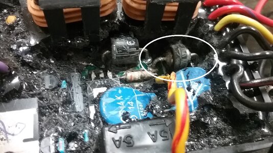
I am a machinist by trade also, I'd rather work on something I can beat on. LOL I had repaired a info gauge for a 1998 and I had the main plug disassembled when I was testing. Big mistake, my hot test wire touched another wire and now all I get is "888888" I'm thinking it blew a diode. Electronics is my growth area as well. It's not the understanding but the knowing the components and ordering the correct one. I went into the MPEM on my 1996 SPI and took pictures of the location of the components. I haven't seen any other pictures of that on the internet. I have a MPEM for a RFI that has a bad rev limiter I'd like to replace and a jet boat that likely has a bad rev limiter as well. If I could get in there.... I'd give it hell. LOL Here is a picture of the MPEM . I tend to get ugly with digging at time and thankfully these obviously not that fragile. LOL

The circle is the diode that blow when voltage come back to the MPEM in the wrong direction. My rectifier failed and caused that to happen.

1996 SPI MPEM Diode Repair (9).jpg
 
I'll look at my gauges and see which ones I don't want. That must have been a pain to replace the screen. Wow !!
Message me and send me your address.
 
It looks like a bomb exploded in there.
Had a barely productive day with my ski due to a case of the droppsies. It also doesn't help that my hands are large as all get out. Weather permitting I will get more accomplished today
 

Attachments

  • Learning Project.pdf
    686.7 KB · Views: 2
  • 20220814_175005.jpg
    20220814_175005.jpg
    273 KB · Views: 11
  • 20220402_101942.jpg
    20220402_101942.jpg
    385.8 KB · Views: 10
  • 20210907_184221.jpg
    20210907_184221.jpg
    271.5 KB · Views: 11
I'll look at my gauges and see which ones I don't want. That must have been a pain to replace the screen. Wow !!
Message me and send me your address.
What is the kicker is that I am willing to try again even though if history is an example, I will be lucky if I don't screw up a 2nd time.
 
Last edited by a moderator:
Status
Not open for further replies.
Back
Top