Bonmotwang
Well-Known Member
The fuel gauge on my Seadoo 97 XPS was work last year. Yesterday I took it out to kick off the season. I noticed that the fuel gauge was not working.
Took apart the connector on the two wires from the baffle. and measured the resistance between the two pins. It was about 5M to 8M Ohms. So open circuit. Connector resistance should be between 0 Ohm to 90 Ohms.
Searched forum, realized it is fuse blown. And looked at other people's pictures and had a plan for my fix. I thought it will be helpful by sharing it. Not rocket science, but my way.
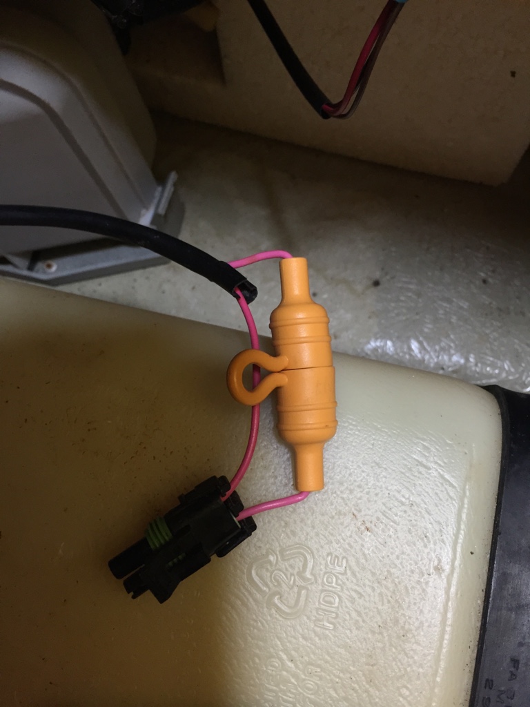
Step 1) Unplug the 2-wire inline connector for the fuel level sensor.
Step 2) Disconnect the four hoses on the baffle. (Vent and Return were reversed, but it doesn't matter, could be either way, search forum you will have more info about this topic). On the battle the name are labeled clearly. (Cut out some tie wraps in the way)
Step 3) Loosen both clamps, I totally backed the clamps open so that it won't scratch my hand while turning and pulling it.
Step 4) Loosen the screw on the back of the choke puller, so that it is hanging free, otherwise it will in your way when you pull the long (10 - 12 inches) baffle tube out.
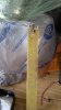
Step 5) Need your muscles: Hold on the black rubber and turn it a little to make sure it is turning, and keep turning back and forth while pulling up. It is very hard to put your 100% strength on it. But be creative and find a way to get it out. I used a big flat screwdriver and pried a little. Believe me you will get it out. Thanks Waterluver, I was going to give up.
Step 6) When the rubber is out, pull the whole thing all the way up, and when it is at the very top, push the wire and cable around a little, wiggle a little, then you will have it.
Step 7) This is what you will have:

remember to cover the fuel tank opening with a piece of something using a elastomer band.
Step 8) Remove the filter screen at the bottom. Just push the 3 snaps in and remove it.

Step 9) The float will drop out. The magnet (cylinder shape) is secured well. Don't think it will fall out in this design. (previous version do fall out).

Step 10) Muscle and being creative again, to slide down the rubber boot. As you can see in the following picture, there is a step the rubber has to overcome to get out. I used a big flat screw driver to pry. The rubber is pretty strong, so you can be a little rough to it. (putting it back is harder LoL).
Step 11) Chance of the the fuse brow if your meter is showing open circuit or mega ohms of resistance. If you are being techy and want to make sure, there is a way. You can actually access the through hole fuse one the bottom side of the PCB (where reed switches and resistors are on). Here are some pictures and I will explain how.
This the PCB top side looking from the bottom of the tube. All the component are on the top side, and the pin are soldered on the bottom side of the PCB.

Here is a link in our forum with the tube opened, if you want to understand more after the location of the components, check out this thread.
http://www.seadooforum.com/showthread.php?69191-Sorry-Fuel-Baffle-Story
Here is a picture of looking into the "RET" hose nipple.
You can clearly see two pins side by side, but there are not the pins for the fuse. What we want is closer to your eyes, and you can barely see them. They are inline with the tube, so you can only barely see one.

So the idea is to short it our using a small screwdriver or Allen key and on the meter the resistance between the two pins in the connector should read around 90 Ohms (the float is out, so no reed switches are closed). What I did is put the allen key through the nipple and feel it is stopped by the two pins which are not belong the fuse, then pull the allen key back and feel the two fuse pins. and push on the side ways. Try a few times, you should be able to short out the fuse and get 90 Ohm reading on your meter. But you can skip this techy step.
[Step 12] OK, Time to cut it open, but I didn't cut, I drilled. 1/4" bit is OK.

Drill 3 holes side by side, so that you can see them, and you can work with your soldering iron. Any debris dropped in, just shake it out from the bottom of the tube.

[Step 13] Now you see the pins belong to the fuse. first soldering step is to presolder/touch the pins. This will make the next step (solder on a jumper wire) much easier.
This is the tools I used. If you don't have the similar size, then probably you can adjust the hole size when drilling to be suitable to your tool size.


Just put the solder beside the pin, and use the soldering iron to melt the solder to sit a drop (about 2mm diameter ball thing) of solder flowing around the pin. If no satisfied result, do it again. Don't keep your soldering iron on the pin for longer than 20 seconds, it may overheat the foil and foil will come off the PCB. You should be OK, I got the "ball" to cover the pin fairly easily. Unfortunately I missed the picture. But do the pre-soldering, it is very important to get the next step right and happy. BTW, you can verify "short to get 90 ohms" here if you want to")
[Step 14] Solder the jumper wire.
You can get a piece of wire (3/4" will be OK) for shorting out the two pins. Leads from 1/4 resistors are the best, but can be anything similar. Also, pre-solder it to cover the whole short wire will solders. Here is the wire before you put it in the tube:

[Step 15] Solder the the wire in. Use a pair of tweezers. Get one end on first then push the other end close the other pin, then solder the other end. Here you will appreciate the pre-soldering you have done!

Here is my work. Not too bad and most importantly, meter is showing 89.5 Ohms. Yahooieeee!
If you get to this step and didn't have too much of soldering experience, congratulations! Well done.
You may say the next step is to cover the hole/slot. But I didn't do because I figured A) the opening is going to be at the neck of the fuel tank opening, so mainly covered. B) the rubber boot will seal. If there is some gasoline jumped out of the opening we drilled, it will just sit between the two big clamps. Please point it out if this is a problem and why.
[Step 16] Put the rubber back and the float and the filter. It took me good 30 minutes to figure out the right way and put it back because you can only put it back from the bottom of the tube. Again I used a flat screwdriver to pry it. Thanks boot, your are pretty strong. This is how I pried:

Just be careful when you get tired and frustrated, don't put any force on the pink and pink/black wires, if they are broken, the tube is dead. Just be patient and creative here. If failed 3 times, try the 4th. Several times I almost got 60% above the step, but it slid back. But take your time, you are almost there!
Then put the float back in, you may found it may stuck on the top, but it is ok, a little tap on the tube it will drop down. This is because over the years, the top part got shrunk a little.
Then put the filter back, if it is dirty, rinse it.
Then you will have this:
Yes, I cheated, it is the first picture. LoL.
Now it is the real time to do double Yahooieee!
[Step 17] put the tube back into the tank, the pink and pink/black wire pointing to where the inline connector was. Again to get bottom into the tank you need to wiggle a little. It is much easier to get the rubber boot back on. Then put the two big clamps back. Then connecting the 4 hoses back, you may debate with yourself which is vent which is return. Flip a coin and follow it. LoL
[Step 18] Tie wrap wherever you see necessary
Put the lanyard on, you will see the fuel gauge back to work! Good job. But I have to point out one thing ignored by most of people and thinking it is not important:
The fuse, yes, why there was a fuse there and inaccessible by the end user.
This is to prevent the 12V circuit or any other power supply from getting somehow shorted to the pink and pink/black wire, it won't become a heater greater than 6W.
The tube is considered as a component in explosive environment, and required by CSA to be a safe device by itself. The only way is to put a fuse in the circuit and not changeable/replaceable by end user. If it was a inline fuse, people may put a 1A or 10A fuse in or just short it out.
So don't complain, Seadoo did the right thing.
Said that, many people may think they are sitting on a bomb while riding it if we short out the fuse. Nahh, it is OK, chances it will blow up is about 0.000214%. Correct me if you have more accurate number.
Please get an inline waterproof fuse holder and 250mA slow blow fuse ordered, so that you can put it in the circuit when it arrives 6 days later. I would put it on the baffle side of the connector on the pink wire. Disconnect the battery first. And put a red tag saying : "250mA fuse slow blow only, do NOT short it".
OK, that is it. happy riding and be safe.
Took apart the connector on the two wires from the baffle. and measured the resistance between the two pins. It was about 5M to 8M Ohms. So open circuit. Connector resistance should be between 0 Ohm to 90 Ohms.
Searched forum, realized it is fuse blown. And looked at other people's pictures and had a plan for my fix. I thought it will be helpful by sharing it. Not rocket science, but my way.
Step 1) Unplug the 2-wire inline connector for the fuel level sensor.
Step 2) Disconnect the four hoses on the baffle. (Vent and Return were reversed, but it doesn't matter, could be either way, search forum you will have more info about this topic). On the battle the name are labeled clearly. (Cut out some tie wraps in the way)
Step 3) Loosen both clamps, I totally backed the clamps open so that it won't scratch my hand while turning and pulling it.
Step 4) Loosen the screw on the back of the choke puller, so that it is hanging free, otherwise it will in your way when you pull the long (10 - 12 inches) baffle tube out.
Step 5) Need your muscles: Hold on the black rubber and turn it a little to make sure it is turning, and keep turning back and forth while pulling up. It is very hard to put your 100% strength on it. But be creative and find a way to get it out. I used a big flat screwdriver and pried a little. Believe me you will get it out. Thanks Waterluver, I was going to give up.
Step 6) When the rubber is out, pull the whole thing all the way up, and when it is at the very top, push the wire and cable around a little, wiggle a little, then you will have it.
Step 7) This is what you will have:
remember to cover the fuel tank opening with a piece of something using a elastomer band.
Step 8) Remove the filter screen at the bottom. Just push the 3 snaps in and remove it.
Step 9) The float will drop out. The magnet (cylinder shape) is secured well. Don't think it will fall out in this design. (previous version do fall out).
Step 10) Muscle and being creative again, to slide down the rubber boot. As you can see in the following picture, there is a step the rubber has to overcome to get out. I used a big flat screw driver to pry. The rubber is pretty strong, so you can be a little rough to it. (putting it back is harder LoL).
Step 11) Chance of the the fuse brow if your meter is showing open circuit or mega ohms of resistance. If you are being techy and want to make sure, there is a way. You can actually access the through hole fuse one the bottom side of the PCB (where reed switches and resistors are on). Here are some pictures and I will explain how.
This the PCB top side looking from the bottom of the tube. All the component are on the top side, and the pin are soldered on the bottom side of the PCB.
Here is a link in our forum with the tube opened, if you want to understand more after the location of the components, check out this thread.
http://www.seadooforum.com/showthread.php?69191-Sorry-Fuel-Baffle-Story
Here is a picture of looking into the "RET" hose nipple.
You can clearly see two pins side by side, but there are not the pins for the fuse. What we want is closer to your eyes, and you can barely see them. They are inline with the tube, so you can only barely see one.
So the idea is to short it our using a small screwdriver or Allen key and on the meter the resistance between the two pins in the connector should read around 90 Ohms (the float is out, so no reed switches are closed). What I did is put the allen key through the nipple and feel it is stopped by the two pins which are not belong the fuse, then pull the allen key back and feel the two fuse pins. and push on the side ways. Try a few times, you should be able to short out the fuse and get 90 Ohm reading on your meter. But you can skip this techy step.
[Step 12] OK, Time to cut it open, but I didn't cut, I drilled. 1/4" bit is OK.
Drill 3 holes side by side, so that you can see them, and you can work with your soldering iron. Any debris dropped in, just shake it out from the bottom of the tube.
[Step 13] Now you see the pins belong to the fuse. first soldering step is to presolder/touch the pins. This will make the next step (solder on a jumper wire) much easier.
This is the tools I used. If you don't have the similar size, then probably you can adjust the hole size when drilling to be suitable to your tool size.
Just put the solder beside the pin, and use the soldering iron to melt the solder to sit a drop (about 2mm diameter ball thing) of solder flowing around the pin. If no satisfied result, do it again. Don't keep your soldering iron on the pin for longer than 20 seconds, it may overheat the foil and foil will come off the PCB. You should be OK, I got the "ball" to cover the pin fairly easily. Unfortunately I missed the picture. But do the pre-soldering, it is very important to get the next step right and happy. BTW, you can verify "short to get 90 ohms" here if you want to
[Step 14] Solder the jumper wire.
You can get a piece of wire (3/4" will be OK) for shorting out the two pins. Leads from 1/4 resistors are the best, but can be anything similar. Also, pre-solder it to cover the whole short wire will solders. Here is the wire before you put it in the tube:
[Step 15] Solder the the wire in. Use a pair of tweezers. Get one end on first then push the other end close the other pin, then solder the other end. Here you will appreciate the pre-soldering you have done!
Here is my work. Not too bad and most importantly, meter is showing 89.5 Ohms. Yahooieeee!
If you get to this step and didn't have too much of soldering experience, congratulations! Well done.
You may say the next step is to cover the hole/slot. But I didn't do because I figured A) the opening is going to be at the neck of the fuel tank opening, so mainly covered. B) the rubber boot will seal. If there is some gasoline jumped out of the opening we drilled, it will just sit between the two big clamps. Please point it out if this is a problem and why.
[Step 16] Put the rubber back and the float and the filter. It took me good 30 minutes to figure out the right way and put it back because you can only put it back from the bottom of the tube. Again I used a flat screwdriver to pry it. Thanks boot, your are pretty strong. This is how I pried:
Just be careful when you get tired and frustrated, don't put any force on the pink and pink/black wires, if they are broken, the tube is dead. Just be patient and creative here. If failed 3 times, try the 4th. Several times I almost got 60% above the step, but it slid back. But take your time, you are almost there!
Then put the float back in, you may found it may stuck on the top, but it is ok, a little tap on the tube it will drop down. This is because over the years, the top part got shrunk a little.
Then put the filter back, if it is dirty, rinse it.
Then you will have this:
Yes, I cheated, it is the first picture. LoL.
Now it is the real time to do double Yahooieee!
[Step 17] put the tube back into the tank, the pink and pink/black wire pointing to where the inline connector was. Again to get bottom into the tank you need to wiggle a little. It is much easier to get the rubber boot back on.
Then put the two big clamps back. Then connecting the 4 hoses back, you may debate with yourself which is vent which is return. Flip a coin and follow it. LoL[Step 18] Tie wrap wherever you see necessary
Put the lanyard on, you will see the fuel gauge back to work! Good job. But I have to point out one thing ignored by most of people and thinking it is not important:
The fuse, yes, why there was a fuse there and inaccessible by the end user.
This is to prevent the 12V circuit or any other power supply from getting somehow shorted to the pink and pink/black wire, it won't become a heater greater than 6W.
The tube is considered as a component in explosive environment, and required by CSA to be a safe device by itself. The only way is to put a fuse in the circuit and not changeable/replaceable by end user. If it was a inline fuse, people may put a 1A or 10A fuse in or just short it out.
So don't complain, Seadoo did the right thing.
Said that, many people may think they are sitting on a bomb while riding it if we short out the fuse. Nahh, it is OK, chances it will blow up is about 0.000214%. Correct me if you have more accurate number.
Please get an inline waterproof fuse holder and 250mA slow blow fuse ordered, so that you can put it in the circuit when it arrives 6 days later. I would put it on the baffle side of the connector on the pink wire. Disconnect the battery first. And put a red tag saying : "250mA fuse slow blow only, do NOT short it".
OK, that is it. happy riding and be safe.
Last edited by a moderator: