DeanBrantley
Active Member
So I went ahead and cut open my gas gauge to see what made it tick, it was broke anyways. Bought a new one for $15 not bad.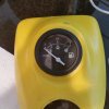
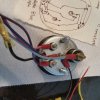 These are the pics. The problem: I want to hook up a low oil level light just like the old one. So I bought a 14v led to mount above the gauge. The oil level sensor looks like it is a straight on/off type switch so it seems that the light should hook like this. LIGHT: Red/positive to the purple power lead on gauge. LIGHT: black/neg to blue lead going to oil level switch. OIL SENSOR WIRE: blue black wire to gauge ground (black). Now if we look at the circuit board we see how the old attached light was mounted on the board
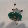 here are other pics showing the board and my diagram.
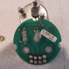
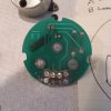
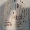 I hope this would be the correct way to wire the light, now what about that pesky resistor??

 These are the pics. The problem: I want to hook up a low oil level light just like the old one. So I bought a 14v led to mount above the gauge. The oil level sensor looks like it is a straight on/off type switch so it seems that the light should hook like this. LIGHT: Red/positive to the purple power lead on gauge. LIGHT: black/neg to blue lead going to oil level switch. OIL SENSOR WIRE: blue black wire to gauge ground (black). Now if we look at the circuit board we see how the old attached light was mounted on the board
 here are other pics showing the board and my diagram.

 I hope this would be the correct way to wire the light, now what about that pesky resistor??


