• This site contains eBay affiliate links for which Sea-Doo Forum may be compensated.

96xp vts gauge is wrong

Minton33

Member
I just picked up and got running a 96 xp for 600$. Hadn’t been licensed since 2016. As the title states my vts gauge is wrong. It goes up and down with the trim but at all the way up, on the gauge it shows just barely more than all the way down. With trim down, on the gauge it’s way below down. Would be awesome if anyone had any ideas what to look for there.

Side note. The fuel gauge doesn’t work, but I know what to look for there. I Assume from past experiences the speedo doesn’t work iether but haven’t took it out yet

It appears someone put a new sbt engine in it before letting it sit for 10 years. 160 on one cylinder and 170 on the other. It’s spraying water out underneath the manifold as well as from one of the exhaust plugs. hoping it’s the manifold gasket and I don’t have to pull the cylinder.

I’ve done the carbs, removed all old fuel and oil, replaced oil lines, new starter+solenoid, new wear ring, new carbon seal, new vts boot, and prolly more I’m not thinking of. It already had fuel lines replaced. Someone let me know if they can think of anything else I should check.

Very excited to ride it after all I’ve heard about them.
 
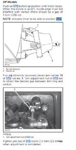
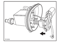
here is the "mechanical calibration, but that should not change anything for the meter because there is an internal limit up and down in the VTS box, from where the "values" come, And what I understand, that is NOT adjustable.
If I remember it right this small "pin" slides in an "slot"in the housing, and then the Resistance ( ohms) is changing
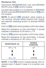
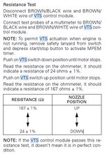
But look if something is corroded, because if readings is always "low" then your resistance is to low.

Measure and compare to this "table". if You have for example a reading of 140 ohm in upper, you can test to add an resistor at 20ohms in serial ( cut the wire and resistor in there, and test what could be the best to "re calibrate" so you hav eYour gauge in the postition)

But start wit all connectors in VTS and Gauge and all other connectors there in between, for bad connection.
Can also be inside Gauge, som bad connection, so open it if it do not help with the external connections, and as a last step test with to addd an resistor.

1754986634906.png1754986544550.png
here is also a pic of the mechanical calibration
1754987079555.png
 

Attachments

  • 1754986616905.png
    1754986616905.png
    76.3 KB · Views: 0
For the Speedo, it is for 99% the sensor that is not working..
here is a really good thread how to rebuild the speed sensor.
it is in this same 2-stroke discussions

SeaDoo Speedometer sensor fix instructions​


But test it first.. put multimeter in DC voltage, measure cables to sensor, one probe to Minus to other to plus.
when you rotate the paddlewheel at sensor it should fluctate fourth and back, from 5,5VDC to something between 8-10Volt.. ( when the magnets ( paddles) on wheel go past housing) depending on Your battery status
 
here is the "mechanical calibration, but that should not change anything for the meter because there is an internal limit up and down in the VTS box, from where the "values" come, And what I understand, that is NOT adjustable.
If I remember it right this small "pin" slides in an "slot"in the housing, and then the Resistance ( ohms) is changing
But look if something is corroded, because if readings is always "low" then your resistance is to low.

Measure and compare to this "table". if You have for example a reading of 140 ohm in upper, you can test to add an resistor at 20ohms in serial ( cut the wire and resistor in there, and test what could be the best to "re calibrate" so you hav eYour gauge in the postition)

But start wit all connectors in VTS and Gauge and all other connectors there in between, for bad connection.
Can also be inside Gauge, som bad connection, so open it if it do not help with the external connections, and as a last step test with to addd an resistor.

View attachment 68309View attachment 68306
here is also a pic of the mechanical calibration
View attachment 68310
Good info. I had not thought of adding a resistor if nothing else works. I will check the ohms out this afternoon. I would think any bad connections would add ohms instead of taking them away so I am suspecting a problem with the sensor or gauge
 
For the Speedo, it is for 99% the sensor that is not working..
here is a really good thread how to rebuild the speed sensor.
it is in this same 2-stroke discussions

SeaDoo Speedometer sensor fix instructions​


But test it first.. put multimeter in DC voltage, measure cables to sensor, one probe to Minus to other to plus.
when you rotate the paddlewheel at sensor it should fluctate fourth and back, from 5,5VDC to something between 8-10Volt.. ( when the magnets ( paddles) on wheel go past housing) depending on Your battery status
I was not aware you could rebuild them. If I can get it to work I’ll have to do the same on my boat.
 
Last edited:
Yes, look at the guide it is an hallsensor and a zenerdiode. so it is very Easy, do you also hav ewater temp there is an "thermo resistor" also added
parts for a couple of $.
and Yes as You said when coroded it Adds Resistance, but how knows how it can behave if it kind of shortens or something

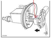
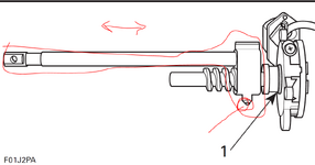
In the pic below, It is this shaft that is coming out in the AFT, ant there is a little screw on it that goes along a "resistor/magneto" inside the Housing, and that changes the resistance/signal to gauge ( but that is totally closed wit h somekind of Epoxy, i think it is impossibke to open that without braking something).
But open up all Mech. stuff and clean, and check that this screw are in right place, and thats part are OK ( somebody can gave opened and Modded before)
then You also can move this by hand, and see how it will "impact" on Your readings and Gauge.


1755072251729.png
1755072054689.png
 
Don't mess with the little hump thing. It is only a magnet and it is in the correct location. Been a long time but I'd say you need to run the motor to the "all the way up" position then adjust the nozzle to have the proper clearance at that position. after that it won't matter and your gauge should read properly. I even cheated a bit on mine because the front end was bouncing. Good Luck !!
 
Interestingly. It was already adjusted almost perfectly. Testing it, all the way up was 180 and all the way down was 30. So I’m guessing it’s a gauge issue. I wonder though if I was to put the correct resistor in there if it would still bring it up to the correct spot.

The bottom of the fuel sending unit is gone as well as the float. The side of it is cracked also. I can plastic weld the side so not worried about that but what’s the easiest way to go about getting the float and bottom piece back out of the tank? Appreciate all the info so far
 
Last edited:
I generally empty all the fuel out of the tank and clean them up as part of my restoration. I get every spec I can out. You can get a small grabber from the auto parts store. They are very handy. I have a long and short. Your already gonna need to pull the tank forward to remove the baffle. I send my baffles to a guy on ebay and he repairs them and sends the back. 50 bucks last time I sent him a couple. Good Luck.
 
I generally empty all the fuel out of the tank and clean them up as part of my restoration. I get every spec I can out. You can get a small grabber from the auto parts store. They are very handy. I have a long and short. Your already gonna need to pull the tank forward to remove the baffle. I send my baffles to a guy on ebay and he repairs them and sends the back. 50 bucks last time I sent him a couple. Good Luck.
Thank you. I actually just took the choke cable loose as the nut was already loose and the baffle came right out with tank still in position. Is there anything else holding the tank in aside from the filler hose and the straps? Hoping the oil tank can stay in.
 
Back
Top