Update
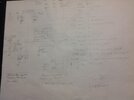
I measured the ohms for the wires that run from the injectors to the ECU. All are good, close to zero ohms.
The throttle position sensor has 3 wires to it. The orange is 6.3 volts. The TAN/black is 1.6 volts. The Lite Blue is 1.8 volts (at idle throttle) and 3.5 volts (wide open throttle) I am guessing this is good
The ECU amps (red wire, multi pin connector 6 ) is 85 mA when the key is ON, zero when the key is off.
and the purple wire multi pin conn 7 (switched +12 from the key) is 10 mA key On, zero when key is off.
[so the ECU is drawing current, i guess that is good] [is was expected higher current ???]
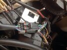
The Fuel Pump and Fuel Primer Relay are controlled by the ECU box. The Black/red wire goes to pin 2 on the multipin connector. When the key is turned on the ECU grounds this wire for about 10 seconds. About 5 amps is flowing thru the Black/red wire into the ECU and can also be seen on the Black wire, pin 18 on the multipin connector going back to ground. This is the clicking sound (Fuel Primer) and hum (Fuel Pump) you hear when the key is turned on. I hope the ECU computer is controlling this but it may be a separate timer IC.
Oh man, this is not looking good. All thats left are 3 wires that come the Control module, spark timing I suspect. I will get the oscilloscope out again and check these.
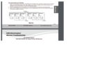
Also the ECU is 240 EFI ECU 824003A31
edit - all 3 wires out of the Control module have a voltage pulse about 3 volts amplitude and occurring what looks like one pulse per revolution. Exactly what I would expect.
So darn, there is nothing left but a failed ECU.