captain scale
Active Member
I have a 1997 GTX and when I first rode it the speedo inputs were erratic and gave an intermittant reading on both gauges. I suspected it was either a poor connection or a bad paddle wheel. I gave up on diagnosing the source of the problem for a while but now I'm back at it. I've never been satisfied with anyone's methods for accurately testing for proper operation so I did some careful thought tonight to find a sure way of testing it. It's so easy a caveman could do it, well as long as he had a 12V test light and some jumper wires.
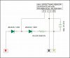
Okay first I redetermined which wires went to what since there are 3 wires. One of them is ground (Black w/Orange), one is the temp signal (White w/Orange), and one is the speed signal (Purple w/White). You can test the temp operation by connecting an Ohm meter to the Black and the White wires and throw some ice cubes on top of the paddle assembly and instantly see the resistance value go up. To test the paddle operation take one end of your test light and hook to your negative battery post. Take the other end and hook it up to the Black lead on the sender pigtail. Then take a Jumper wire and hook one end up to the Positive battery post and hook the other end to the Purple lead on the connector. Depending on the postition of the paddle wheel the light will either be on or off. If you slowly rotate the paddle you will see the test light go on and off. If you give the wheel a spin you will see the test light flicker! I like this method because you don't need a voltmeter to test with and you can visibly see a response even in low light. I happened to be testing this tonight outside in the driveway!
I am happy to say that my sending unit seems to be working flawlessly so now I simply have to search for a poor connection in the wiring harness. I suspect it is somewhere at the front of the ski where the harness goes up into the hatch cover. That's where my last one had a problem. Those wires get bent back and forth a lot every time you open and close the hatch. They are also more vulnerable to water intrusion because the bow sometimes gets inundated if you crash through a wave or lean hard into the water in a turn!
It's interesting that the fuel guage and speedo use the same basic technology to generate a signal. The fuel guage uses a long circuit board with magnetic reed switches and a resistor for each along with a float containing a permenant magnet to generate a signal. I suspect that the speedo either uses a reed switch or a ferrous sensor as a switch and a magnetic wheel to generate it's signal, much like a crankshaft or camshaft sensor on an automobile.
So, I'm basically looking for a poor connection somewhere. But, with the help of my ohm meter I sould be able to track it down.