• This site contains eBay affiliate links for which Sea-Doo Forum may be compensated.

Sportster Depth Finder Transducer Location

Status
Not open for further replies.

despower

Active Member
I have seen a number of posts regarding the installation of hull puck transducers on Challengers. Kustomkarl made an excellent post in Nov 07 on the installation of a Hawkeye HP transducer that provides a good start to my problem. In my case, I would like to install a Uniden HP transducer in my 2006 Sportster. Kustomkarl's pictures of the location of HP transducer near his jet look very similar what 'could be' a good location within my engine compartment. Nonetheless, if anyone can post a few photos of where they located their HP transducer in their Sportster, I would be most appreciative.

Regards...

Des Power
 
Hmmm. Not so much response thus far. How about I widen the field a bit. If anyone out there has installed a in-hull transducer in a Speedster or Sportster of any model year, can you post a pic of where you epoxied the transducer?

In particular, I am curious about the proximity of the transducer to the jet. I have uploaded a pic of my engine compartment and pointed to the approximate location of kustomkarl's transducer on his Challenger. As you can see, my engine compartment doesn't have that 'depression' near the engine so I am wondering if I could install the transducer underneath the engine. Any ideas?

Note that I don't have the depth finder yet (ordered it a few days ago) so I can't experiment with various locations in the engine compartment.

When I do get the unit, and find a good location for an install, I'll post, along with some instructions (assuming I get it working of course).
 

Attachments

  • Sportster_2006_Engine copy.jpg
    Sportster_2006_Engine copy.jpg
    812.4 KB · Views: 425
I've been contemplating installing one into my 06 sportster as well.
I'm looking forward to your pics
 
I don't understand the confusions... Just find a place in the hull of the boat that is forward, or to the side of the turbulent water and mount it. I always put about 2 inches of water in my boat bottom and set the transducer in place, in the water, and turn it on to see if it shoots through the Hull. When it gives me the depth...( have to have the boat in the water in 2' or deeper) I mark it, dry the bottom real good and add my 2 part, slow cure epoxy in place and let it set overnight. DONE.

Karl
 
No confusion really... I just wanted to see the general location of a transducer install on a Sportster. But I guess you are saying that it should be in the same general area as where you installed your Challenger's transducer.

My Uniden depth finder arrived a few days ago and I managed to install it with the help of my shop manual and the photos of kustomkarl's electrical hookup photos. The gauge installed easily (I had a 2 1/8" blank behind my steering wheel) and now all I have to do is install the transducer. I will find a good location when I set the Sportster into the water and test out where the transducer works on the hull.

The Uniden transducer is one of those that allow you vary the shoot angle of the transducer for deadrises up to 22 degrees. Instead of epoxing the transducer to the hull, a mounting bracket gets placed onto the hull with silicone, then filled with mineral oil or glycol. The transducer then screws right into the bracket so that the oil/glycol serves as the acoustic coupler to the hull.

I'll post some photos when I get it done.
 
It sounds like you got it under control. It really is a simple thing to do. I do about 10 a year and only once in a while run into a problem with a transducer location.
Pics would be a good thing for other members to see, as I usually don't have a camera in my hands while doing a project.

Karl
 
Thanks.

One other thing... looks like you are working on the assumption that I actually know what I am at. :lols:

I'll post some pics in a couple of days, assuming the weather holds up (10C today... a bit too chilly even for me). So far, the hardest thing I had to do was remove the steering wheel (without a steering wheel pulling jig).
 
uh....steering wheel for a depth finder? :ack:

Let me know it you need anymore help.

Karl
 
The steering wheel had to come off because there was a 2 1/8" gauge blank behind the wheel. The wheel had to come off, along with a plastic cover face plate so that I could remove the gauge 'blank' and replace it with the depth finder. So, no drilling required at all. It is hard to describe without photos... those will come shortly.

So far so good. Gauge is installed and wires are routed around to the engine compartment. I tested the transducer ins a bucket of water and the readings are good. I'll post the first set of pictures tonight.
 
Pictures of install thus far

Below I provide instructions for what I have done so far to install the Uniden Depth Finder gauge. I have included photos and screen grabs from the shop manual to help out.

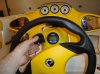
Photo A - shot of steering wheel and location of depth finder gauge. As you can see, there is a Uniden Gauge above the steering column. This was the gauge that I installed.

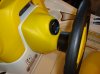
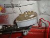
Photo B - shot of blank. This is the gauge blank that needs to be removed so that the new depth finder can be installed. How nice that they put in a blank 2 1/8 hole for the gauge. No cutting required. I tried to pry the blank off, not realizing that the blank was screwed in place. Luckily I had the shop manual to show me that the blank was screwed in place.

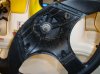
Photo-C - removing wheel. To remove the blank, you have to remove the steering wheel with a 3/4" socket and a bit of muscle. The shop manual suggests using a steering wheel removal tool so that you don't damage the wheel. That would be nice to have, but I didn't have it. I just pulled it off. My Sporter isn't that old so the wheel wasn't fused in place. Nonetheless, I had to use a bit of extra force to pull it off once the nut was taken off.

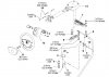
Photo D - from shop manual. Shows that you have to remove the 3/4" nut and wheel (11). Also, to get at the nuts from behind the blank, you have to remove the steering column cover (12). This can be removed by removing the 4 bolts from the back of the steering column cover (not shown here). You get at these by lifting the console up and removing the storage bucket.

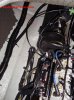
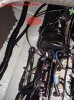
Photo E - front inside the console. Here is a shot that shows the back of the steering column cover and 3 of the 4 nuts that have to be removed to remove the steering column cover. These are hard to get at. You can see that I ran the transducer wire and the power/ground through the gap between the steering column.

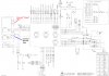
Photo F - This is the wiring diagram from the shop manual. I connected the red power wire of the depth finder to SP4 which is a junction for 4 purple wires coming from the other gauges (tach, speedo, etc). I connected the black common wire to SP3 which is a ground point near SP4. Both SP4 and SP3 are underneath the console behind the steering wheel.

Note that you could also connect to the Yellow-Orange wires at SP5 which is also +12V. However, Yellow-Orange circuit is "on" all the time except when the battery switch is set to off. The purple circuit only comes on when you insert your key and turn the motor on.

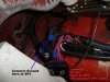
Photo G - This is the photo of SP4 and SP3 where I made the connections for my power and ground. Note that here, the wrong cap has been placed on SP4 so it looks like it is SP1. I was confused by this for a while since I was referring to the wiring diagram, but this cap must have been wrongly put here by a service tech. I routed the transducer cable along the inside of the hull where a few other wiring harnesses are routed to the engine compartment.

Looks like I can only upload 5 photos with this post, so the next post will be the rest of the photos.

In a few days I will post the photos of where I installed the transducer.

Thanks to Karl's previous posts for help on doing this. I don't know if any of this adds any value for others trying to do this, but i figure I had a lot of help with the shop manual and maybe not everyone has one of these.
 

Attachments

  • A-SteeringWheel.jpg
    A-SteeringWheel.jpg
    308.3 KB · Views: 299
  • B-Blank.jpg
    B-Blank.jpg
    402.2 KB · Views: 315
  • C-RemoveWheel.jpg
    C-RemoveWheel.jpg
    434.3 KB · Views: 242
  • D-SteeringWheelRemoval.jpg
    D-SteeringWheelRemoval.jpg
    176.3 KB · Views: 249
  • E-SteeringColumnCoverRemoval.jpg
    E-SteeringColumnCoverRemoval.jpg
    707.8 KB · Views: 360
And here are the other photos...
 

Attachments

  • F-electrical copy.jpg
    F-electrical copy.jpg
    541.5 KB · Views: 197
  • G-WireConnections A.jpg
    G-WireConnections A.jpg
    658.5 KB · Views: 334
I'm curious on the transducer location - did you post any pics of the transducer yet? Looking forward to seeing them
 
Sorry about not posting and update to this recently. In fact, I have only had the Seadoo out once this season, and I had trouble getting a good reading from the transducer even with the transducer placed directly in the water and not on the hull. I suspect I had the gain set too high - the gain adjustment is, in fact, behind the gauge, and is difficult to get at. This is obvious from the photos that I posted - what I have to do is to remove the mounting bracket for the gauge so that I can adjust the gain. I shall be doing that the next time I have the boat on the water.

If anyone else has used a Uniden depth finder, I would appreciate some feedback on the transducer gain setting that you used (mine is currently cranked up to the max, which was the default setting).

It might be a week or two before I get the boat on the water again (the weather isn't cooperating here), so it might be a while before I post another update.
 
Finally I had the Sportster out yesterday and it was fairly easy to locate the optimal location for the depth finder HP transducer. I used the "bag full of water trick" - put the transducer in a ziplock bag, filled it full of water, and moved the bag around along the hull in the engine compartment until the depth finder gave a sensible readout (same as the readout when I dropped the transducer over the side). A photo of the location is attached.

Lo and behold is it about the same spot in the engine compartment as Kustomkarl's Challenger installation (see http://www.seadooforum.com/showthread.php?t=1093). For those having difficulty figuring out the photo, it is on the starboard side of the engine compartment, almost to the stern and to the left of the jet. In the photo, I just moved the hoses to oneside, placed the bag there and voila. It looks like it could be anywhere in the vicinity of that location, almost to one foot back from the transom. As you can see, the hull isn't exactly level there, but the uniden transducer has a jig that allows the adjustment of the transducer firing angle from 0 - 22 degrees, so it would be a snap to align it for nadir.

Next photos will be the final installation and (hopefully) successful operation. This won't be posted for a few weeks because I am headed out of town and won't be able to complete the install until I get back.
 

Attachments

  • Transducer Location.jpg
    Transducer Location.jpg
    809.9 KB · Views: 382
best humminbird transducer for sportster

I have a 2004 sportster 4-TEC and I'm trying to mount the transducer for a hummingbird fish finder. I don't know whether to use the transducer that came with it or use hummingbirds exchange program for the one meant to be glued in the hull or has anyone tried using the kayak removable mount that uses marine lube and a tie down ?
 
I would think that a 'tie down' transducer would be hard to mount, just because the location to mount the transducer is hard to get at. My transducer could be mounted with silicone sealant (as opposed to epoxy) so if I screwed up and mount it in a non optimal location (which i did) it is easy enough to remove and try again.
 
Thanks for the reply
By the looks of your avatar you have the same boat as ours seeing how you have Already gone through the trial and error process of finding the correct location it would be greatly appreciated if you could either post photos are give me an accurate description of the best location to mount the transducer .in my application I have to epoxy it in
So I cannot afford to make mistakes
thanks
 
If you look back through this thread, you will see the photo you are looking for - I already posted it. Nonetheless, I highly recommend that, given you are going to epoxy this in, you try the 'bag method' - i.e., put your transducer in a plastic ziplock bag filled with water and put it in the location that I have indicated in the photo and make sure the transducer works there (i.e., you get a proper reading from that spot relative to dropping the directly transducer into the water).

Or just avoid using epoxy and use silicone sealant instead. I am sure that will work equally as well as the epoxy.
 
Status
Not open for further replies.
Back
Top