ripcuda
Active Member
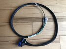
I bought the Mercury CDM Test Harness made by CDI Electronics. This is the one that goes between the CDM (coil module) and the wire harness that plugs into it. It gives pigtails for the 4 wires so you can measure voltages while cranking/running (with CDM still connected) using a DVA as described in the service manual.

I probed the harness to confirm how it is wired. It is very straight-forward. No diodes or resistors or anything. Just simple wire pigtails off the 4 main wires.
Note: the BLK/YEL (kill) wire is cut between the connectors and 2 separate pigtails are given (one male, one female) so you can connect/disconnect the kill wire when testing.

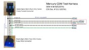
I made a simple wiring diagram in-case anyone wanted to build their own.

The trickiest part will be finding a Metri-Pack 150.2 series MALE connector. The female connectors are easy to find, but the males are not. I read somewhere that this series was meant for plugging into things (like distributors, TPIs, CDMs, etc.) and as such did not have male connectors. The male connector used by CDI is actually a cut-off part of some sensor. You can see where they cut it free and connected their wires to it. So that may be your best option for a male connector. It gets the job done.
Cheers!

I probed the harness to confirm how it is wired. It is very straight-forward. No diodes or resistors or anything. Just simple wire pigtails off the 4 main wires.
Note: the BLK/YEL (kill) wire is cut between the connectors and 2 separate pigtails are given (one male, one female) so you can connect/disconnect the kill wire when testing.

I made a simple wiring diagram in-case anyone wanted to build their own.

The trickiest part will be finding a Metri-Pack 150.2 series MALE connector. The female connectors are easy to find, but the males are not. I read somewhere that this series was meant for plugging into things (like distributors, TPIs, CDMs, etc.) and as such did not have male connectors. The male connector used by CDI is actually a cut-off part of some sensor. You can see where they cut it free and connected their wires to it. So that may be your best option for a male connector. It gets the job done.
Cheers!


