I was musing about installing battery disconnects on my machines (2000 EX and 1997 GTI (modified to GTX spec), in order to simplify the battery maintainer/charging system. To wit, I always disconnect the positive cable when I have them on the charger, and at least on the RX that's a bit of a hassle with taking off one of the air tubes, etc. My thought is to put a low-profile disconnect, flush mounted on the side of the hull, connected to the positive battery cable. One assumes that with the switch in the 'off' position, one could charge the battery without having to disconnect the cable?


-
This site contains eBay affiliate links for which Sea-Doo Forum may be compensated.
You are using an out of date browser. It may not display this or other websites correctly.
You should upgrade or use an alternative browser.
You should upgrade or use an alternative browser.
battery disconnects, anyone?
- Thread starter bajaman123
- Start date
Yeah...good point.Most aren’t water proof and just another point for corrosion and issues.
CrocDundee
Member
I just use butterfly nuts and undo the positive after each day.
You should be removing the negative. Negative always comes off first and goes on last. Less chances of arcing.I just use butterfly nuts and undo the positive after each day.
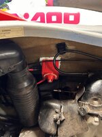
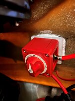
Well, after careful consideration, I went ahead and installed a disconnect and a charging port. Everything installed is "marine rated", for what that is worth and I double shrink wrapped all the connections and put an anti-corrosion coating on battery-related components.
Attachments
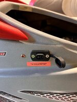

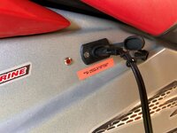
Bajaman123: very nice! A few questions: (1) what does the light mean? Engine running (thus charging the battery)? (2) do you have a rough schematic of the wiring of the disconnect and light? or did you follow something on youtube or somewhere? The less I try to invent myself the more likely I'll get it right! ")
The light means the battery is 'ON' so do not boost it. There's a little decal by the port that notes this.Bajaman123: very nice! A few questions: (1) what does the light mean? Engine running (thus charging the battery)? (2) do you have a rough schematic of the wiring of the disconnect and light? or did you follow something on youtube or somewhere? The less I try to invent myself the more likely I'll get it right!
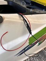
The installation is pretty straightforward; probably the biggest hurdles are you have to make a mount and bond it to the inside of the hull, I used some 1/2" thick nylon plastic sheet I happened to have lying around, and the next one is you have to cut the battery cable lug off as it has a 1/4" hole in it, and the disconnect (at least the one I used) has 3/8" posts. Generally speaking it takes a pretty heavy duty crimper (which I did have) to crimp these lugs onto the battery cable. You can do it reasonably well with Vise-Grips as you're going to heat-shrink it anyway. You will also have to make another heavy-gauge battery cable up. So my steps were:
- cut a 3" X 3" piece out of the nylon sheet, position the disconnect on it and pre-drill the mounting holes using a 1/16" drill. On the back side, drill a dozen or so holes about halfway through to give the adhesive (I used 3M fast cure 4200) something to grip).
- find a suitable mounting spot, clean the inside of the hull with xylene or carb cleaner, acetone, etc. NOTE! make sure the positive cable from the engine will easily reach this or you will have to make an extension.
- liberally apply the 3M 4200 to both the hull and the back of the block then position the nylon block and clamp into place. For this I did have to order some long reach clamps. Let set up for 24 hours.
- while the adhesive is curing, crimp and heat shrink a 3/8" lug to the positive cable from the engine. This becomes the cable that connects to the OUTPUT side of the disconnect switch
- purchase a suitable length 4 gauge battery cable, making sure it has 3/8" lugs. Cut the lug off one end and crimp and heat-shrink on a 1/4" battery cable lug. This will be your cable from the INPUT side of the disconnect, to the battery. My first one I bought was 12" which ended up being just a little bit too short, and I ended up buying a 18" version.
- Once the adhesive has cured on your mounting block (this is why I like the fast cure versions of 3M 4200 and 3M 5200), mount the cables to the appropriate terminals; OUTPUT goes to the engine positive battery cable (the original cable), INPUT goes to the battery cable you made up that goes to...the battery. IF you are going to install the tell-tale light, fabricate a wire (preferably red) of 18 gauge about 3' long, crimp a terminal connector that has a 3/8" hole, install this terminal on the OUTPUT side of the disconnect switch. Leave the free end hanging out. Fasten the disconnect switch to your mounting block using the supplied screws. Depending on how much room you have to work, you may find it necessary to use a 90 degree drill adapter of some sort.
- So now you should have the disconnect switch mounted to your hull, with two heavy gage cables coming out of it...with one attached to the engine harness and one ready to attach to the positive terminal on your battery. You will also have the small, 18 gauge wire that will go to the positive wire on the tell-tale light (if you are using it).
- Now it is time to make the connections to the battery. This is where you will install your Battery Tender wires to your battery, both positive and negative, You will also at this point have to make the negative wire connection for your tell-tale light if you are doing that...simply make another 3' long 18 gauge wire (preferably black). So your battery will have the following wires on it: positive side; heavy gauge wire from the INPUT side of the disconnect; positive wire from the Battery Tender harness wire you made. Negative side; heavy gauge negative wire from the engine harness; negative wire terminal from the Battery Tender, and negative wire from the tell-tale light.
- Test the switch. In the OFF position you should have no power to the engine. Turn the switch to ON, you should be able to start the engine.
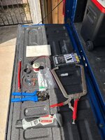
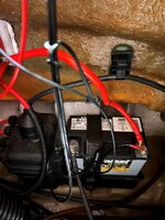
Here is what it looks like on my GTI...you can see the switch, the cables, the battery and battery tender terminals, and the wires being run for the tell-tale light. I am getting ready to make the hole for the charging plug and installing it and the tell-tale light.
Attachments
jdabramson
New Member

That is a good solution, I looked into that but simply didn't really have the room or easy access to the battery.I've had this one installed for a year now. No signs of corrosion.
MACSBOOST Powersport Battery Mount Cut-off Switch
View attachment 67815
Similar threads
- Replies
- 2
- Views
- 784