• This site contains eBay affiliate links for which Sea-Doo Forum may be compensated.

1999 challenger 1800

Status
Not open for further replies.

fonthillhdtv

New Member
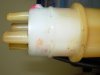
Got my boat out of storage I am new to the seadoo boat thing so I have a
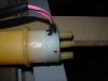
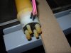
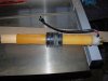
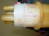
ton of questions. Last fall I noticed that the motor on the starboard side has a clogged water line that comes out of the bottom of the motor and runs to the back out to the pee hole I can see some crystals in the line that are clogging it.how would you guys recommend clearing it as I cannot get to the connection under motor.
gas gauge is also not functioning I need to determine if it the gauge or the sender any ideas.I looked at the baffle last night the clamps on the fuel lines ,do they undo or will I need to cut them and replace them with stainless clamps.
I have a beeper issue with the dss when I intall lanyard I can hear 2 very faint beeps replaced buzzer same issue.how do I go about testing when it only beeps the 2 times can I disconnect something to make mpeg think I have a fault and
get a continuous beep so I can check connections with a voltage present.
 
Just cut the oklier(sp?) clamps off and use Zip ties to replace them, check the fuel float, these can be bought at the deal for < $10....
 
I got the baffle out trying to test it now. in every thread i have found they talk about using an ohm meter across the two wires on the baffle and read the meter as the float moves my baffle has three wires which 2 do i have to read across. The float sound like it has gas in it and the magnets are pretty corrode so i think it needs replacing but i get no reading as it moves up and down the baffle I think maybe the f1 fuse is blown.
 
Maybe the fuse is blown, are you sure the magnet is there? Try using another magnet, if not the fuse is blown which is still an easy fix...

Three wires? Huh....I've only worked on the 2 wire ones..
 
I uploaded some pictures of the baffle it is different from the one in the thread in how to soldier the f1 fuse .Can anyone tell me if the same procedure holds true for this 1999 challenger baffle. Notice the 3 wires on this one. would the f1 fuse be in the same place love to know before I start to cut it open
 

Attachments

  • DSCN0594.JPG
    DSCN0594.JPG
    101.5 KB · Views: 186
  • DSCN0592.JPG
    DSCN0592.JPG
    95.6 KB · Views: 163
  • DSCN0591.JPG
    DSCN0591.JPG
    94.9 KB · Views: 172
I also have a 99 Challenger 1800 and last weekend fixed the fuel sensor. You need to check the resistance between the pink and pink/black wires. If it shows open, then it is the F1 resistor.

The fix as described in this forum is relatively easy and it took maybe an hour. I opened the hole with a razor blade since the plastic is very soft. The trick is where to open the hole so that you don't have to keep making it bigger to find the right spot. The F1 resistor is actually quite close to the flange and a little to the right if looking normal to the internal PCB plane in the upper portion of the tube, in the side opposite to were the cables exit the unit. BTW, I congratulate you for being able to slide the rubber boot down. As hard as I tried I couldn't do that. I slid mine up over the wires, using a little lubrication on the rubber to help. A little scary since I tough I could damage them but it is doable.

The third wire (pink/white) is the low fuel warning system. It turns on a light and activates the beeper. this system is not in the same circuit as the gage and F1 resistor but I think it is activated by the same magnetic switches. If you check resistance between pink/white and pink/black you will find that it works similar to the gage circuit but he resistance will not change until the float is almost at the bottom.

Last, I don't understand what you mean by the two faint beeps when you insert the lanyard. I thought that is what you get when all is well. They are faint on mine (I think they are very short).

Chris
 
Thanks for replying i'm glad you tried to explain where to cut but i don't understand I have the baffle in my hand opposite where the wires are are two pickup tubes "on " and "ven" .I'm not sure what you mean by the flange I will post another pic and maybe you could mark on it where to cut . a razor blade will cut the plastic? that would be cleaner then a dremmel.
The buzzer is so faint you can hardly hear it. when i got the boat it used to make a very distinct beep that i could hear over the engine noise.
 

Attachments

  • cut location.JPG
    cut location.JPG
    33 KB · Views: 185
  • DSCN0597.JPG
    DSCN0597.JPG
    104.7 KB · Views: 168
I hope I didn't confuse you too much :)

NO don't cut the area you show. YES, that is the flange I am referring to but you need to cut on the bottom side (toward the tank). I know, when I said "opposite to the cables" it was very confusing.

The one thing I did to help me locate the fuse was pop the cover with the filter on the bottom of the tube and look at the PCB inside. If I remember correctly, the fuse is in the side were all the magnetic switches are soldered in the board, almost at the top of the PCB and toward the right side. There is a good picture of how the PCB looks form the bottom toward the end of the sticky.

Check the great sticky in the how-to's that talks about this repair. The link is

http://www.seadooforum.com/showthread.php?t=5826

If you look at the pictures on the sticky, they show a window on top and below the "flange". You need to open the one below the flange to reach the F1 fuse.

Study the sticky, it is quite clear. Make sure you confirm you measure an open between the pink and pink/black wires with an ohmmeter before you do this repair (to make sure F1 is your problem). Try the pink/white and pink/black wires. That probably still works OK.

I am not an expert so please check around in the forum but I hope this helps. As I said, I did the repair and it worked great. I had never welded using plastic ties as filler material and that was a fun first.

Chris
 
Last edited by a moderator:
Thanks for your help, the repair is finished and the gas gauge works great. Check out the attached pictures. I wanted to make sure of the location exactly so I took it to work with me and x-rayed it with a dental x-ray machine then just measured off the xray and cut. I labeled one of the xrays so the next person to do this repair would know exactly where to cut. The flange you spoke about shows up as a lighter line the plastic pin I noted on the xray is visible when you look up the tube from the bottom. The F1 fuse even showed up in the xray as a open circuit between the two posts.
PS- I am a technical rep with a company called Patterson Dental that sells Dental equipment.
 

Attachments

  • xray f1 fuse.JPG
    xray f1 fuse.JPG
    129.2 KB · Views: 431
  • xray with measurements.JPG
    xray with measurements.JPG
    32.2 KB · Views: 408
  • f1 fuse.JPG
    f1 fuse.JPG
    90.1 KB · Views: 419
I just wanted to say thanks Chris. The razor blade idea was the answer for me. Super easy, and even easier to weld back together. I have a 97 Seadoo XP, and these instructions were perfect for that as well. Thanks Everyone!
 
Status
Not open for further replies.
Back
Top