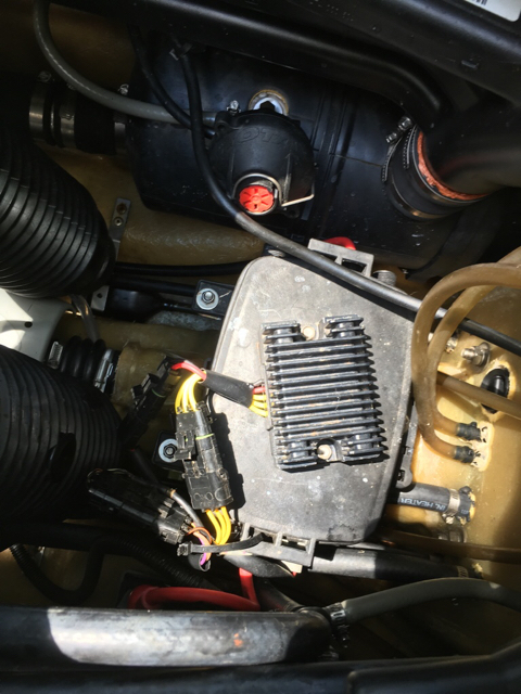
Just out of curiosity, has anyone ever dug out the potting compound to get to the electronics in a regulator / rectifier? I understand, from some of my more electronics-skilled buds that there should only be a diode set in there.
Since I am going to get a new one, I may get the old Dremel out and dig out the bad one, just because.
Short answer to your question is yes, and there are more than just a simple diode bridge in these.
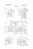
Several years back I looked up and found Tympanium's patent, there are several designs of course for different applications, some single phase and three phase, some shunt and different types of bridges.
The one I suppose is used by Seadoo for the 3-phase system is shown in figure 5 of this 1st drawing poated, and the "control item 26" circuit detail is figure 7, seems like to me. Remember, there are ways to beef up a regulator by using larger diodes and SCR's capable of handling more current thus as time has progressed the higher amp circuits have been beefed up accordingly, of course. This would be your 4-tec regulator. This is a patent thus, exact components selected aren't specified, it's the design that counts.
So I was curious as well and dug the potting out of a Typaniukm regulator for a project. I found the mounting screws for the SCR's were lose, this regulator had stopped working and was defective, occasionally it would work but mostly it didn't.
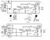
In the 2nd drawing poseted, I copied Tympanium's regulator circuit and installed it in an old non-regulated Sears battery charger using the original diodes and added a single SCR with the regulator to gate the SCR, you know the type of charger we used to deal with, ones that can boil out a battery in short order if left unattended. Well, it was just sitting in the back of the shop unused so why not?
My modified battery charger is the upper half of drawing.
So this old battery charger works like an automatic charger now, it regulates at 14.2 volts on high xfmr primary setting and 13.7 on low xfmr primary setting. Does a great job of charging batteries and doesn't boil them out, yea!
")
Not as sophisticated as a real good float charger but great for leaving a battery for a week at least, no lost sleep wondering if a puddle of acid will be on the bench in the morning.
I also worked out the circuit to eliminate the diodes but it requires two SCR's, more expensive by $1 but one fewer components, LOL Shown in lower half of drawing FWIW.
Cheers!