VTS quit working, just hear a click

Note: This site contains eBay affiliate links for which SeaDooForum.com may be compensated
Status
Not open for further replies.

jimmaki

Active Member
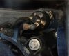
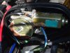
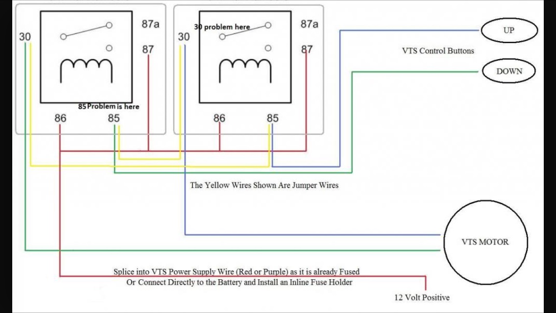
The VTS on my 98 SPX just quit working. When I press the up or down button, all I hear is a click coming from the VTS module. I opened the VTS oval motor box and found a lot of water corrosion inside. I disconnected the motor leads and jumped them straight to the battery and the motor appears to be working in both directions. So from what I gather the switches are working, the relay is working, and the motor works when connected directly to the motor. I assume the fuse is ok because of the clicking relay. I can't tell from the schematic if the fuse protects just the motor or all the power to the VTS module/motor.

If the motor is working is there benefit to taking it apart while I have it out? The round cover over the worm gear appears to be a metal cover that is crimped on. Not sure how to get it off and then how to secure it back on.

I'm thinking of drilling a hole in the bottom of the case to let water OUT as the box obviously isn't as sealed as the gasket and boot should appear to make it.
 
The seal goes bad often and then smokes the motor. The VTS module is a very common failure. I think the relay is within the module though. If it were mine, I would test for output from the module depending on what switch you push.
 
Lots of info here on the VTS fix and why it breaks. The gurus will direct u soon. I been where u r so here is my experience. First you have to decide if u like or really need it. I love it. Others don't care. It allows me to adjust the doo ride according to the water conditions choppy smooth ect. If u don't want it you can disconnect it and set it in the middle position. Some do this. Others fix it. Taking the VTS module apart and fixing the module seems to be beyond the DIY unless you have some electrical background or a lot of time to digest the literature on it that I found on this forum. In the end I checked the fuse first in the black rear electrical box. Then I checked the motor. Then the switch then I bought a used one from Minnetonka on this site. The install directions are on this site as well. If u decide to do the job another member made a tool out of pvc pipe that you can make easily to remove the worm nut in rear to get the VTS module out.
I will watch this thread if the gurus don't post u the links soon I will look for them but I know these guys are great and have them ready. Give them some time they help many people all day but need to live also.
Also I would become a premium member if you are going to keep the ski. Well worth it.
 
I just tested the VTS module output and the up button sends 7.2 volts DC across the motor wires (motor disconnected). The down button output at the motor wires reads 0.022 vDC. The battery reads 12.24 vDC on the same Fluke 77 meter at the same time. Any sense checking the fuse? They don't go "half bad" right? If it were blown I would think I'd see zero volts either button.
 
There is a slight chance you still have a fuse issue., but not likely. I have seen some corrode and deliver less than the required volts and amps needed. The module is a very common failure. If you find you have no fuse issue, remove the VTS fuse as it has been known to damage the MPEM. If you still want your VTS, you have one of two options. Replace the module or do the $20 VTS Fix.


Sent from my iPhone using Tapatalk
 
Here is the cheap fix. You build this and eliminate the VTS Module.

109.jpg


Sent from my iPhone using Tapatalk
 
I'd really prefer to have the VTS working (depending of course on the cost and amount of work to get it working). It doesn't really do much for me anymore to just go flat out as fast as I can back and forth and see how much pain I can endure. I guess I could just hang my head out the car window at 60mph, throw a pail of water on myself and beat my head with a 2x4 and get the same thrill. :) No offense to those who like it. I like the ability to tilt up the nozzle and stand at the back of the boat and do vertical turns, then turn the nozzle back down and do horizontal spins. Different strokes.

From what testing I did, it looks like the VTS module is toast. From what I can tell, all the electronics are encapsulated in epoxy or something and since I don't know where the board and components are underneath, I imagine it's a crap shoot to grind the epoxy away without possibly doing more damage than good. Then there's the seemingly widespread opinion (reading other theads) that the module is a design failure anyway, so why fix or replace it since it's only a matter of time until I get to put more time and aggravation into fixing the same problem?

I've read elsewhere that some think this problem can be solved by jury rigging up some relays but so far I haven't seen any details before those threads were locked. It's a shame because the motor works, the worm gear turns freely, and the guage reacts properly to the position of the slide as I manually turn the worm gear and watch the nozzle go up and down (this is with the motor disconnected and removed)

I saw a product called TrimFix or something like that which is an aftermarket box that replaces the VTS module and is externally mounted and supposedly doesn't have the frailties of the OEM VTS module. Anyone here heard good or bad about this aftermarket alternative? I'm not against buying and installing a new or working used OEM VTS but it's a bit of work, and not inexpensive, especially if it's a continual, repetitive chore. I don't know what blew the VTS in the first place so I'd want to figure that out and fix it before putting in another VTS module, OEM or aftermarket. I think, it was salt water getting into the motor and lowering it's impedance and pulling excessing amps through the VTS and blowing a semiconductor. But since the fuse didn't blow I am still pondering that theory.

I'll look into premium membership but I've already got all the manuals, parts lists, etc., plus I can't figure out how to upgrade.
 
Thanks for the cheap fix schematic, but I'm not sure what the numbers represent. I looked at the shop manual wiring diagrams and schematics thinking the numbers came from there but all wires on the schematic (and the boat) are marked by color, i.e. PU-WH, BW-BK, GR-WH, BR-WH etc. Also what is/are the "85 problem" and the "30 problem"? Where does one get the relays assuming they are waterproof. Is this set up able to use the existing limit switches?
 
I was resisting checking the 7.5amp fuse since the box it's in was just about impossible to get into. The starboard side of the electrical box and the locking tab on that side is so close to the inside wall of the boat I couldn't get a finger in there to depress and release it. Finally got it depressed with a screwdriver coming in from the side, not the top. Despite clicking relays and 7 volts at the motor wires, the fuse was blown!

[EDIT] Upon further examination of the electrical box clearance problem, the interference is really not the inside wall of the boat but a foam floatation "bag" that expanded during manufacture and left very little room to get to the catch release. I may cut the foam out in that area to facilitate future access. I also notice the gasket was badly deformed on that side (rolled over) and was probably damaged during manufacture since I've never opened that box before and am the original owner. There was about six ounces of water in the bottom of the box but no noticeable corrosion on any parts. The 7.5 amp fuse contacts were dull gray. The 15 amp fuse looked cherry.

Before I put a new 7.5 amp fuse in and give things a go, after reading your message I'm somewhat paranoid now about blowing the MPEM until I figure out what blew the fuse in the first place. Not sure what further diagnostic tests to run to protect the MPEM against a "new fuse" test. If I disconnect the MPEM to protect it while I test, the VTS should still work, yes? Does the 15 amp fuse in the same box protect the MPEM? If the engine isn't running will removing that 15 amp fuse in the rear box protect the MPEM from VTS testing? I take it the MPEM is what the schematic calls the Electronic Module MAPP? The box up front on the port side of the fuel tank? It appears the RE-PU wire off the 15 amp fuse in the back goes into this box up front to power it?
 
Last edited by a moderator:
I would think so. Most VTS issues are a result of the seal failing and letting water in.


Sent from my iPhone using Tapatalk
 
The seal on the box itself seems to be ok. I looked from the back and the bellows seal appears to be ok although I have not removed the white plastic ratchet clamps to see if the rubber underneath is cut. I felt around all the bellows creases for any obvious cracks/openings and didn't feel any. Before I put things back together I'll replace that bellows with a new one and inspect the old one better once it's off the boat.

[EDIT]

Good news to report ... I took a ohm reading from the protected side of the 7.5 amp fuse to ground using a good fuse in backwards so I clipped onto the fuse lead hanging out of the fuse block. I got 11.86 Mohms so relieved there was short, I went ahead and put the new fuse in the right way and ran the voltage check at the VTS motor leads (motor disconnected) and got 12.4VDC and -12.4VDC respectively hitting the up and then the down buttons on the handlebar. So ... hopefully this means the VTS module is o.k.? (for now) I took a reading across the motor leads and got 5.8 ohms. So I'm estimating a no load draw of about 2 amps, maybe up to 3x that with a load with nozzle pressure . But that would still be within the 7.5 amp fuse limit. These numbers seem o.k. or should I keep looking for a cause for what initially blew the fuse? I'm sure things were different when the motor was wet but I don't want to test that theory.

If water in the VTS module is the mostly likely culprit causing failures, besides maintaining good seals ... has anyone tried, either A) drilling a drain hole in the bottom of the VTS box to let the water out, or B) cutting a vertical window in the VTS cover and sealing it from the inside with a piece of clear plexiglass with silicone sealant, or C) putting a petcock valve instead of just a hole in the bottom of the case so water can be drained and then the petcock closed afterwards. I'm thinking of the small petcocks like you see on the bottom of water separator/filters used with air compressors.
 
Last edited by a moderator:
Sounds like you are headed on a good path.

I can't answer what others have done to resolve the water issue. I only know what I have learned from others having issues...
 
The only place water gets in is from the accordion seal that is in the back of the jetski. If your the original owner and have never replaced it, chances are it has failed. If water got in, I highly doubt it came from inside the ski. Unless it was sunk! So replace the seal and grease the rod. The seal is a cheap fix also. This is what happens when you don't keep that accordion seal fresh......


Sent from my iPhone using Tapatalk
 
Probably a bad motor. I love the VTS. I don't know why so many people say it's a minor feature and not worth fixing. Riding my 96XP ski between trim all the way up and all the way down is like 2 different skis. Trim up and she will come out of the water at even the smallest wave, spin out easily, and get crazy high air. Trim down and she will stay planted in the water, allowing the ski to turn hard on a dime without sliding. Love the contrast!
 
I hear you, the internal gasket looked fine. I still haven't taken off the boot to get a good look at it. It has some plastic clamps that I'm not quite sure how to open. I've tried lifting the outer tab with a screwdriver, but there are also teeth between the middle and inner part so it looks like the outer and middle legs have to be lifted simultaneously. A bit hard to get two hands, two screwdrivers and still see in there all at the same time. Hopefully I won't have to take off the pump to get to them. Is there a name for these clamps (see picture) and a special tool to release them?

The insides of my VTS weren't quite as bad as the picture you sent, but there are signs it definitely had water in it at some point. The motor appears to be working as well as the VTS module but I haven't hooked it all up back together again yet. I'm wondering if I should try to open the motor and check for problems inside, but since it works I'm hesitating since I might do more damage than good. The screw holding the motor magnet cover on are rusted in pretty good. I've tried atf and an impact screw driver but so far no go.
 

Attachments

  • VTSBoot.jpg
    VTSBoot.jpg
    283 KB · Views: 67
  • VTSMotor.jpg
    VTSMotor.jpg
    282.3 KB · Views: 70
I think if my VTS had gotten toasted and I couldn't find parts or afford to fix it, so much of the fun of the ski would be gone I'd most likely sell it. Heck half the fun is turning on a dime *AND* sliding sideways (and backwards)! Equally fun is tilting the nozzle all the way up and standing the ski on it's rear with the nose straight up and do 360's in one spot. Gee, given the rear ends spends so much time buried in the water ..... I wonder how water got into the VTS??? :)
 
I have the VTS motor out and it works but since there are definite signs water was in the VTS motor box at one point, I'm wondering if now would be a good time to try and open it and check for further damage. Only thing that has stopped me so far is the screws holding the motor cover on are so badly corroded I can't get them off with penetrating oil and an impact screwdriver (the kind you hit with a hammer), or any kind of screwdriver. Should I at least clean and repaint the outside? Every swimming pool pump I've had to replace was because the cases rusted from the outside in and as the case wall swelled, allowed the magnets to rub on the armature. So I'm a little leary of steel motor cases around water.
 
Last edited by a moderator:
I hear you, the internal gasket looked fine. I still haven't taken off the boot to get a good look at it. It has some plastic clamps that I'm not quite sure how to open. I've tried lifting the outer tab with a screwdriver, but there are also teeth between the middle and inner part so it looks like the outer and middle legs have to be lifted simultaneously. A bit hard to get two hands, two screwdrivers and still see in there all at the same time. Hopefully I won't have to take off the pump to get to them. Is there a name for these clamps (see picture) and a special tool to release them?

The insides of my VTS weren't quite as bad as the picture you sent, but there are signs it definitely had water in it at some point. The motor appears to be working as well as the VTS module but I haven't hooked it all up back together again yet. I'm wondering if I should try to open the motor and check for problems inside, but since it works I'm hesitating since I might do more damage than good. The screw holding the motor magnet cover on are rusted in pretty good. I've tried atf and an impact screw driver but so far no go.

If you can't easily open it, don't. Coat it up with CRC Lubricant or something similar and call it the day. I would get any details off it while you have the chance in the event it fails. There is some car window motors that will work and are MUCH cheaper. SO write down any numbers you find and maybe make a picture with measurements on it.


Sent from my iPhone using Tapatalk
 
Good advice, I may leave well enough alone, it's easy enough to get to if it fails down the road. I already cammed out the screws holding the check valve in one of my Mukini BN38s. I'd hate to lose the whole carb trying to get them out. I tried an EZout but no luck, those guys are in there but good.

There two stickers on the VTS motor, one is green and the writing is so faded I can't read it. It looks like an inspector's stamp of some kind. The other label is a bar code sticker. I think that might be the part number?
 

Attachments

  • VTS bar code.jpg
    VTS bar code.jpg
    188.5 KB · Views: 54
Good news and bad news ...

The good news is I got the VTS motor back in and tested it and it works using the up/down buttons on the handlebar! The gauge and position sensor are working! As if that weren't more than one could expect, the other good news is I don't have to wonder anymore what blew the 7.5 amp fuse in the first place.

The bad news appears to be a faulty up limit switch in the VTS module. The tilt will auto-stop in the down direction, but going up it will pin the meter and the motor/nozzle and I can hear the motor straining. Didn't take long to blow the new 7.5 amp fuse I just put in. Just for grins I disconnected the MPEM and found I can repeatedly blow fuses by waiting just a second too long holding the up button. That's a second over no seconds.

Are the limit switches mechanical or some Hall effect devices? If the latter where are the magnets? Maybe one just fell out or something similar to the fuel guage magnets <fingers crossed>.

If it's not a loose magnet but a bad Hall effect transistor buried deep in the epoxy ... has anyone here tried the TrimFix aftermarket black box? I believe it uses the position sensor for the dash meter to determine where the tilt unit is so it can limit the tavel. I don't know how it is adjusted for end to end trael or if you get whatever they set at the factory. Any experiences here with this? Good or bad.
 
Install one of these. It is a resetting fuse. It will trip internally and when it cools will reset. At least until you do whatever you do with the limit switch.

115.jpg


Sent from my iPhone using Tapatalk
 
That might be worth a try. Naturally I'd stop pressing on the button when the gauge indicates the nozzle is all the way up. But would something like this jeopardize the MPEM if I kept triggering it, accidentally of course? Where might I get one of these without going to the Dominican Republic? :)
 
That might be worth a try. Naturally I'd stop pressing on the button when the gauge indicates the nozzle is all the way up. But would something like this jeopardize the MPEM if I kept triggering it, accidentally of course? Where might I get one of these without going to the Dominican Republic? :)

In theory, no. The theory behind the fuse /resetting fuse is to protect the MPEM. I get what your concern is, but I'd rather have a resetting one in there than none. Which is what it will e when it blows...
 
I found some of those resetting fuses here: http://www.connectorconcepts.com/se22xcibr75a.html They look bigger than the standard size fuses but those water proof cases where the fuses are located in the electrical box are fairly large so the resettable fuse looks like it may fit. They aren't expensive like under two bucks. For the ton of cash they get for the fuel tank baffle they should have designed one in for the t1 fuse as they come in smt cases which are probably less than a penny in bulk.

I ordered two but the shipping and handling to Florida was $16.47, it was the same shipping cost for one or six.
 
Last edited by a moderator:
Status
Not open for further replies.
Back
Top