Snipes Korner...

Note: This site contains eBay affiliate links for which SeaDooForum.com may be compensated
Status
Not open for further replies.

seadoosnipe

Premium Member
Premium Member
At one point, I started an information thread to help members understand the history and working knowledge of the Seadoo PWC/boats, that we as members, have come to love. Now, being in the forum, we are showing, that we also love to do our own work on them. Due to the limitations of the forums typed word count, I will be breaking this post into 3 sections.

The below information is a paste and copy from a google I did, looking for information on a way to those, looking for adjusting the "high" speed screw. Which in our mechancal world is a no,no. Since they come pre-set from the factory. But......some have had the plastic caps removed and don't know where that setting is suppose to be. The below information may help you understand what you can do and what to look for while adjusting these screws.

If you have any questions after this read, please feel free to post and I'll try to help you out. This is the kind of research and reading that I do to further understand my working knowledge of Rotax, outside my already extensive knowledge on their overhaul and tuning. Enjoy the read!

CARBURETOR FINE TUNING GUIDE by Harry & Gerhard Klemm / GroupK
While there seems to be an abundant number of folks selling high performance carburetors and carb kits, there seems to be a desperate shortage of folks providing "understandable" carburetor tuning information. For the 8 or 9 warmer months out of the year, getting a knowledgeable technician to talk to you on the phone about adjusting "your carb on your boat" is darn near impossible.

For the knowledgeable and experienced (read: very very busy) technician, few things are more frustrating than trying to explain fine tuning procedures, along with the history of carburetors, over the phone. It's even more frustrating if that same technician knows it's a carburetor you bought from somebody else (someone who won't help you tune it).

The following is a guide to help you avert being that unwelcome caller. Good technicians, no matter how busy, are usually glad to help someone who has covered all the basics and just requires detail information. The following guide is an easy to understand outline of "those basics". We hope you find them helpful.

UNDERSTANDING SOME BACKGROUND

The two generations of carbs - Before 1989, virtually all pwc's utilized the "round pump" Mikuni carbs. These carbs came in 38mm and 44 mm sizes only. These "round pump" carbs performed well, but they were somewhat temperamental because the round diaphragm pumps often had difficulty supplying enough fuel to high output racing engines. In 1990, both Mikuni and Keihin introduced "square pump" style carbs. The fuel pumps on these carbs produce more than double the fuel pressure of the earlier "round pump" designs. Among other new design features, the square pump carbs also have changeable high speed and low speed jets. These changeable internal jets allow for very accurate mixture adjustment on a broad range of engine formats.

External adjustments - Virtually all pwc carbs have a high speed and low speed fuel mixture adjustment screws. The adjustment screw positioned closest to the air intake (top) is always the high speed fuel mixture screw (30%-100% throttle range). The adjustment screw closest to the mounting surface (bottom ) of the carb is always the low speed fuel mixture adjustment (0-35% throttle range). As these screws are turned out, the fuel mixture is made richer. All adjustment settings are noted as "turns out" from the bottomed out position. That is, "1 turn out" means 1 turn from the bottomed closed position.

Power tuning - Many shops offer "power tuning" as a means of adjusting carburetion. The boat is held stationary in a test tank or on a trailer backed into the water so that adjustments can be made while the engine is running under a load. This type of tuning is adequate for getting carburetion close, however it is by no means an effective way to achieve the ideal mid-range or full throttle carb settings. Power tuning does not simulate the added loads of the water drag on the hull surface, the rider's weight, or high speed water being loaded into the front side of the pump. These collective loads make "riding on the water" the only accurate way of evaluating carburetion settings on a high output watercraft.

Reading spark plugs - Determining proper fuel mixture by inspecting the color and condition of the spark plugs can be very helpful in situations where the engine is being operated constantly at full rpm under full load. "Reading plugs" for perfect fuel mixture is very common in high speed auto and motorcycle racing where the engines are nearly always run at full rpm and full load. Closed course pwc racing, however, requires as much "partial throttle" operation as full throttle. Furthermore a pwc racing engine seldom experiences full steady loads because of the rough water conditions. This means that spark plug readings, done on a pwc that is being ridden on a rough water course, has very questionable accuracy.

To get an accurate plug reading on a pwc, a fresh set of spark plugs should be run in the machine for 3-5 minutes at full throttle/full rpm on relatively smooth water. At the end of the full throttle running, the throttle should be chopped and the kill button pushed simultaneously (called a "plug chop"). If the engine is run at partial throttle for even 3 seconds after the full throttle run, the plug reading will be invalid.

After the full throttle running, and the plug chop, a combination flashlight/magnifying glass must be used to view the carbon deposit at the base of the porcelain (down inside the spark plug where the porcelain insulator and outer steel spark plug casing meet. A ring of dark brown at the base of the porcelain denotes ideal fuel mixture, light brown is lean, and a ring of black is over rich. This is the only area of the spark plug that accurately indicates fuel mixture. Furthermore, this reading only indicates full throttle fuel mixture. No part of the spark plug can indicate low speed or mid range fuel mixture. The upper part of the spark plug porcelain (by the electrodes) is often very light or white in color, however this coloring is mostly affected by additives in the gasoline and oil. The coloring of the end of the porcelain in no way indicates appropriate fuel mixtures of any throttle range. The cosmetic appearance of the spark plugs can defiantly help a pwc mechanic to quickly diagnose the symptoms of a major operational problem. But as far as carb fine tuning for personal water crafts is concerned...reading plugs qualifies as a very questionably accurate way to fine tune the carbs. Very few professional PWC engine builders recommend their customers to do carb fine tuning based on plug readings...and even fewer engine builders do it themselves.

The weather - Weather and altitude can defiantly be a factor during fine tuning. The factors that will require you to go leaner are, higher altitude (changes of 1000 ft. or more), higher temperatures (changes of 20' F or more), and higher humidity (changes of 20% or more). Water temperature itself (55-85'F) seems to have very little effect on fuel mixture. It seems that the big changes in weather that come with very warm water, and very cold water are what actually affect the mixture.

BEFORE YOU ENTER THE WATER

Air leaks - The lower end of a two cycle engine must be air tight to about 10 psi. If there are any minute air leaks at a crank seal or a gasket surface, tiny amounts of air will intermittently leak into the lower end and cause a temporary lean condition. As a matter of reality, about 50% of the engines on an average race lineup have an air leak. Most of those leaks are not big enough to cause chronic hard-starting or piston seizures, however they are usually big enough to cause on-going jetting problems.

As the castings of an engine expand and contract with heat, so too can the air leaks change to admit greater and lesser amounts of outside air during operation.

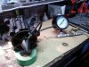
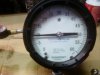
Group K offers an inexpensive pressure test kit that allows you to quickly check for, and locate, any potential air leaks your engine may have. An engine with a small air leak will never carburate consistently. Remember...air leaks never get smaller.

Reeds - If your reed petals are chipped or frayed in a way that does not permit perfect sealing, the low speed and mid range circuits will be very difficult, if not impossible, to set accurately. Damaged reed petals will cause a false low speed rich condition, not to mention hesitations in mid range that you will not be able to carburate out. Installing aftermarket reeds will often require significant changes in cab adjustment.

Carb gaskets - Confirm that these gaskets have a soft drying sealer (like Gaskacinch or Permatex Hi-Tack or 3Bond 1211)on them, and that the carb mounting bolts are torqued.

Confirm full closing and opening - With the flame arrestor(s) off, be sure that the carb butterfly(s) can close completely with the handle pole all the way down and the handlebars in the full left and right positions.

Pressure test fuel system - All pwc utilize a sealed fuel system that has a check valve on the gas tank vent. This check valve (which permits pressure in the gas tank but not out)
 
Last edited by a moderator:
Carbs, Pt.2

causes pressure in the gas tank that helps deliver fuel to the carb(s). Any air leak in the fuel system that permits the leaking off of this pressure, will also affect fuel delivery to the carb(s) at low speeds. To test for leaks, follow this procedure. 1) remove the return line from the fitting on the carb. 2) Blow into the return line while sealing off the return fitting on the carb with your finger. This will pressurize the entire fuel system. In a quiet room you'll be able to hear any remaining leak in the fuel system. When you remove your finger from the fitting on the carb, fuel will eventually drip out indicating that the float chamber is primed full of fuel.

Return line restrictors - The round pump 44 Mikuni carbs were manufactured with an unrestricted return fitting on the carb. This causes them to return so much fuel to the tank that the fuel circuits can get starved for fuel. If you are using a round pump 44 Mikuni, be sure you have a restrictor jet in the return line whose inside diameter is no more than .030" (.75mm) All of the new generation square pump carbs have adequate "built in" return line restrictors.

Spark plugs - Most machines can safely use NGK #8 heat range spark plugs. However, in situations where you're trying to resolve a serious rich condition, it's best to do your preliminary tuning with #7 heat range plugs. After the tuning is done, however, return to the #8 heat range.

Pop off pressure - This term refers to the amount of fuel pressure needed to push the float needle valve away from it's sealing seat. Pop off pressure is checked with a hand pump that is fitted with an in line gage. The pump is connected to the fuel input fitting of the carb. The return line fitting is then sealed off with one finger while the pump pressurizes the float chamber. The pressure reached on the gauge when the needle gives way is called the pop off pressure. "Adjusting" the pop off pressure is discussed below. If you don't have a pop off pressure gauge, you should get one that has a gauge and pump capable of 30 psi. (Most Mikuni distributors carry them) At the beginning, it's only important to check that the needle holds the pressure back with no leaking up to the point where it pops cleanly away from the seat. Perform the pop off test several times to confirm the actual pop off pressure. Initial pop off pressures on round pump carbs should be between 8 - 12 psi. Initial pop off pressures on the square pump Mikuni and Kiehin carbs (unless otherwise specified) should be no less than 25 psi and no greater than 35 psi.

Dual carbs - Racing has certainly popularized dual carburetors. However having dual carbs is not necessarily the passport to big time horsepower. Dual carbs usually require a little more maintenance and on going adjustment. If putting up with that is not your cut of tea, you'll probably get all the performance you need, along with all the simplicity you want, from a good aftermarket single carb upgrade kit. If you've decided that aftermarket "duals" are for you, the pop off pressure between them should not vary more than one psi. Of equal importance, before doing any fine tuning, visually confirm that both throttle butterflies are closing completely and opening at the same instant. When setting the mixture screws, the settings should always be kept identical between the two carbs unless otherwise specified by the carb kit maker or your engine builder.

LOW SPEED ADJUSTMENT 0% to 35% throttle range - In 90% of all cases, the low speed mixture screw can be accurately set without riding the machine. Secure the boat on a submerged trailer or standing in about three feet of water. With the engine completely warmed up, set the carb up to a slightly higher than normal steady idle. Turn the low speed mixture screw in or out in 1/4 turn increments. As you get closer to the ideal setting, the engine rpm's will increase. If the idle speed is increased by this mixture adjustment, turn the idle speed adjustment screw down and continue the same process in 1/8 turn increments. At the ideal mixture setting, 1/8 turn in a richer or leaner direction will cause a very un-steady idle and cause the engine to die. To confirm your perfect low speed mixture setting, touch the kill button during idling...and then touch the start button about ten seconds later. The engine should restart instantly and idle steadily without touching the throttle.

Some race engines with heavy mid range fuel demands may eventually require as much as 1/4 turn richer adjustment from this ideal setting point, however the need for an over rich low speed mixture setting usually indicates an unacceptable lean condition in the mid range. Avoid running an over rich low speed mixture screw setting in an effort to cure a mid range hesitation (lean condition).

If you find that your ideal mixture setting is less than 1/2 turn out from bottoming, you should probably consider going to a slightly leaner (smaller number) internal low speed jet. If you find that your ideal setting is beyond 2 turns out, you should consider a slightly richer (larger number) internal low speed jet.

HIGH SPEED ADJUSTMENT 30% to 100% throttle range - The greatest fear of most racers is that of seizing an expensive engine as a result of running an excessively lean high speed fuel mixture. Some old racers contend that maximum horsepower is attained with a high speed fuel mixture that is at the brink of piston seizure. This fable is not true...and it never has been. Where high output pwc engines are concerned, the ideal high speed mixture is the richest setting that still permits strong acceleration up to peak rpm. With this in mind, it is always wise to start out slightly over rich and slowly lean the mixture out. If the high speed mixture is too rich, the peak rpm's will "sign off" prematurely. If the high speed mixture is too lean, you'll experience weak or "lazy" mid range acceleration.

You'll eventually find a narrow adjustment range where peak rpm operation seems unchanged. However, within this range, there should be a noticeable difference in mid to high range acceleration. Finding the setting, within this range, that gives the best "middle through high range acceleration" usually requires a couple of back to back 10-15 minute evaluation rides.

TRANSITION RANGE ADJUSTMENT 20% to 50% throttle range - The early style "round pump" 44 Mikuni is the only pwc carburetor ever manufactured with an external transition range adjustment screw. On the new generation square pump carbs, the manufacturers have abandoned the idea of this third adjustment screw because it caused so much confusion for the average watercraft owners and mechanics. The transition range of the new generation carbs is adjusted by changing the pop off pressure. These pop off pressure adjustments are made by way of various combinations of needle/seat sizes and float arm spring tensions.

In short terms, the transition circuit is richened by reducing pop off pressure with larger needle/seat sizes, as well as shorter or weaker tension float arm springs. The various combinations of larger needle valves and weaker springs result in a wide range of lower pop off pressures. Measuring the pop off pressure is how you determine whether you have made the transition circuit richer or leaner (higher pressures are leaner, lower pressures are richer) Most racing engines prefer very low pop off pressures because they demand so much fuel in the mid range. Unfortunately these low pop off pressures can often create an undesired (and nonadjustable) rich condition in the 0 - 30% range. This nonadjustable rich condition takes place at about 9 psi on the Mikuni square pump carb and about 13 psi on the Keihin. Running pop of pressures this low is not recommended. Ideally, you want to run the highest possible pop off pressure that permits "hesitation free" mid range throttle response.

AFTER TUNING - After you've found the best settings for your carb, make a record of it. By far the best place for this record is the inside of your hood, written in bold felt pen. Denote the final adjustment settings and the pop off pressure. If space permits, record your high and low speed jet sizes, as well as the day's temperature.


LATENT FUEL PRESSURIZATION - The powerful fuel pumps on the new generation Mikuni and Kiehin carbs has mandated a need for much higher pop off pressures than that of the earlier round pump carbs. Pop off pressures in the 25-35 psi range are very common. Without these high pop off pressures, the powerful fuel pumps would quickly flood the motor. All in all, this combination of a powerful pump working against a high pop off pressure is superior in all functional ways...except one.

When the engine is at rest, the pressure in the fuel system is virtually nil. As the engine is started, there is easily enough fuel delivery and fuel pressure to feed the meager needs of the low speed circuit for idling. However when the throttle of a "just started" engine is drawn slightly, a temporary lean condition of the transition circuit often causes the engine to hesitate badly or even stop altogether. This lean condition takes place because the fuel pump has not yet fully pressurized the float chamber of the carb. The 20% - 50% range transition circuit is solely dependent on full float chamber pressure in order to deliver it's fuel. Full float chamber pressure usually takes place after about 10 or 15 seconds of operation under a load. For a recreational rider who is slowly riding away from the beach , this momentary lack of low speed acceleration is no problem. However for the racer who must start an engine at the line, and operate it at little or no load before the start, this momentary lack of acceleration can be a big problem. If you are running dual carbs, this fuel pressurization problem can become even worse.
 
Carbs...Pt. 3 conclusion

Unfortunately the only mechanical ways to reduce this hesitation problem is to reduce the fuel hose length, reduce the internal air volume of the fuel system, or slightly reduce the pop off pressure.

On most stock fuel systems the pump must draw the fuel through about three feet of hose from the gas tank to the fuel valve. After that, through another two feet of hose and a fuel filter. This long length of hose saps off a significant amount of fuel pressure and increases fuel pressurization times. To help resolve this on race boats, a direct line should be run from the reserve pickup on the gas tank to the carb. Along with this, it should be understood that the air space in the fuel system is the area that must be pressurized. If the air space is reduced by filling the gas tank, pressurization takes less time. Unfortunately many racers don't like the "nose heavy" handling that a full gas tank yields. For them a smaller gas tank is a wise solution.

The risk of inducing an over rich transition circuit mixture makes "pop off pressure reduction" an absolute last resort choice for solving the latent fuel pressurization that takes place in the starting area of a race.

I'd like to credit the authors of this research, Harry and Gerhard Klemm of Group K and more information can be found at the web site: http://www.groupk.com
 
How to read your spark plug!

There is a lot of questions from members, who know when they pull their plug out, it's fouled or it's to lean.........but there are a lot of parameters inbetween.

Because there are so many different visuals on what a plug can look like, I"m going to take the time to try and show, by picture, what your plug may look like, that way, you'll either be able to present your questions better to the forum of your engines running condition or you yourself may find it easier to determine whats wrong with it.

The picutures by number, will start at the richest plugs and end in the highest by the category of "hot" or to lean.

Thanks for your patience in waiting for this thead.

This information was distributed by NGK as a free hand out and posted freely on the Internet. No citing was necessary.

The first 5 plugs, show a rich running condition. This condition is not acceptable for efficient operation and should be corrected by leaning your carb a little. Only adjust by small increments, then run again for 15 minutes before rechecking.
Plug #1 and 2 are oil fouled; #3 is carbon fouled; #4 and 5 too cold.
Plug #6, 7 and 8 are cold or rich, but o.k. (could be leaned just a little).
Plug #9 and 10, 11 and 12 are good.
Plug #13 is real good.
Plug #14 is the best!.......:hurray:
Plug #15, 16 and 17 are best.
Plug #18, 19 and 20 are good.
Plug #21, 22, 23, and 24 are a bit lean, (could be enrichened a bit)
Plug #25, 26, 27, 28 and 29 show obvious signs of over heating from running lean. Pre-ignition is propable. This is a critical problem and should be corrected as soon as possible.

There are two adjustments "low" and "high" speed screws. For the most part, you should never have to adjust the high speed screw. But, if you want to know how to correct these plug conditions, you'll have to observe the plugs in two ways.

To adjust the low speed screw. Idle around for awhile, about 15 minutes. Kill the engine and pull the plugs at that moment, while they are hot. Have a rag available to insulate your hand from the heat. Read the plugs, adjust the low speed screw. Both plugs should read the same and both low speed screws should be adjusted the same. If you by chance show a plug running good and one lean, then you may enrichen just that carb. But, if you find yourself with one low speed screw at 1 and 1/4 turns open and the other 2, to have equal plugs, that means you could have a dirty jet and your correcting the problem by increasing the fuel mixture.

To adjust the high speed screw. This is protected by the manafacturer with a plastic cap becuase the smallest of changes on a high speed screw can be an incredible amout of fuel/air ratio. So I recommend extreme "CAUTION" in doing this. You'll need to run your engine at WOT for about 15 or 20 minutes. The longer the better. Then, while at WOT, kill the engines power. Have all your tools ready before you get started, the plugs will be hot. So gloves or a rag will be necessary. Pull the plugs as soon as the engine is dead. Read these plugs. This reading will be a bit different from your reading at idle speed. If the WOT plug conditions show a sign of running to hot/lean, then you may want to open that high speed screw by just a 12th of a turn. If you see a light rich condition. I'd leave it.

My personal plugs, at high speed, look close to the picture number 18 on both cylinders. I have a 1997, 787cc model engine.

You that use the 951 or 4-TEC engines, have less lee way on your plugs condtions that we who use the 787 and smaller engines. Your engines have higher compression ratios. Your engines work harder to attain the performance that you want in such high speed PWC/boats. So, the condition of your plugs is very important.

Any RFI, DI or fuel injected engine should make these changes through the engines EMS system, so you just double check behind the engine managment system, to make sure it's taking care of your engine as it's suppose to.

I hope this thread helps you identify how well your engines health is. The compression and reading the plug is like your doctor taking your temperature and blood pressure. This are your engines vitals. Please, check them often. You'll find your engines life span may be greatly increased with such little care as maintaining a good fuel/air mixture.

Good luck and happy riding!................:cheers:
 

Attachments

  • oil fouled.jpg
    oil fouled.jpg
    3.7 KB · Views: 542
  • Oil fouled2.jpg
    Oil fouled2.jpg
    7.7 KB · Views: 400
  • carbon fouled.jpg
    carbon fouled.jpg
    6.2 KB · Views: 414
  • Too cold.jpg
    Too cold.jpg
    6.2 KB · Views: 360
  • Too cold 5.jpg
    Too cold 5.jpg
    7.1 KB · Views: 322
  • image006.jpg
    image006.jpg
    7.9 KB · Views: 349
  • image007.jpg
    image007.jpg
    6.9 KB · Views: 243
  • image008.jpg
    image008.jpg
    7.6 KB · Views: 219
  • image009.jpg
    image009.jpg
    8.1 KB · Views: 221
  • image010.jpg
    image010.jpg
    8.9 KB · Views: 217
  • image011.jpg
    image011.jpg
    6.8 KB · Views: 210
  • image012.jpg
    image012.jpg
    6.8 KB · Views: 221
  • image013.jpg
    image013.jpg
    7.6 KB · Views: 291
  • image014.jpg
    image014.jpg
    6.9 KB · Views: 485
  • image015.jpg
    image015.jpg
    7.2 KB · Views: 243
  • image016.jpg
    image016.jpg
    7.5 KB · Views: 218
  • image017.jpg
    image017.jpg
    8.2 KB · Views: 226
  • image018.jpg
    image018.jpg
    6.9 KB · Views: 307
  • image019.jpg
    image019.jpg
    7.4 KB · Views: 194
  • image020.jpg
    image020.jpg
    7.3 KB · Views: 181
  • image021.jpg
    image021.jpg
    6.9 KB · Views: 205
  • image022.jpg
    image022.jpg
    8 KB · Views: 197
  • image023.jpg
    image023.jpg
    7.2 KB · Views: 210
  • image024.jpg
    image024.jpg
    7.4 KB · Views: 193
  • image025.jpg
    image025.jpg
    8 KB · Views: 220
  • image026.jpg
    image026.jpg
    9.2 KB · Views: 193
  • image027.jpg
    image027.jpg
    9.3 KB · Views: 210
  • image028.jpg
    image028.jpg
    7.5 KB · Views: 203
  • image029.jpg
    image029.jpg
    8.6 KB · Views: 287
Last edited by a moderator:
Tuned pipe exhaust repairs........

The demise of our tuned water pipes

There have been many post on the leaks that are occurring on the older model Seadoo’s and their tuned pipes. I have been researching this and made several post about this problem. In my job, I deal with water chemistry daily. The experience of testing and treating water and the problems I’m seeing in the breakdown in the aluminum metals of the Rotax engines tuned pipe, have a relation to the trace elements of the salt (brackish) waters that are used in cooling our engines.

My job is to remove a lot of these trace elements before the water is used in our “pure” process. I use ion exchange, ultraviolet, charcoal filtering, and chemical additives, to control these elements. Unfortunately, we cannot do this to water used to cool our engines. So, to educate you as to what is going on, may be the best way to help you decide in what steps to take when the metal becomes so thin, you develop a leak.

All water contains minerals of some sort, there is no such thing as pure H2O, unless you make it. Salt water has a combination of 70 different elements that are dissolved in the water, but only six of these elements make up 99% of the dissolved salts as ions, which are electrically charged. They are Chloride (55.04% by wt), Sodium (30.61% by wt), Sulphate (7.68% by wt), Magnesium (3.69% by wt) Calcium (1.16% by wt) and Potassium (1.10% by wt).

The electrically charged ions, when heated, leach from the water and cling to the metal surface, in the same way that “chrome plating” works. The mineral build up in the tuned pipe is at its highest concentration because the water comes in as ambient temperature through the cooling water inlet at the pump. It’s sent across the head (depending on what engine, in this case, the 787cc) and then, crosses to the exhaust tuned pipe for the purpose of being pre-heated before going into the engine. The water travels in a circular path around the pipe, to maximize the amount of time the water is exposed to a hot surface. It also has a secondary purpose, it cools the exhaust gases of the engine. The purpose for preheating is to minimize thermal shock from the heat created in combustion of an internal engine. If our engines had thermostats in them, then preheating the water would take place and be controlled by the heat built up in the engine and slowly released and circulated by a variable controlled valve, the thermostat.

Because these minerals absorb the aluminum, creating it to become brittle and cause loss of integrity through decreasing the wall thickness over time, leaks develop. From my experience, these leaks are taking place mostly in the welded plugs but I think it’s safe to say, from my examination of the inner parts that were visible, this is the weakest part of the pipe and eventually, other leaks will develop.

There are several solutions being tried on these pipes. JPX (moderator) has purchased another used tuned pipe, leaving him a spare to work with. Others have taken it to a welding shop and had the leaks cleaned and welded. My choice was to strip the paint away, gently tap on it with a hammer to determine the wall thickness and see if the potential for other leaks was there (one leak developed into 5 holes) and go ahead and drill, dremel these areas out to go ahead and make my fix.

My patching theory and fix: Because the water system at the water jacket has no true solid pressure (it varies by the speed of the jet pump), I used my dremel tool to clean away all the bad spots with a stone and wire wheel attachment. Then, using my drill, with a small bit, drilled hole around the area that was very thin. The holes will be used to help hold the material for patching. Then, I used my drill to make small indentions all over the area, again to help hold the patching compond. With a hole the size of a nickel, I prepared an area the size of a silver dollar to make sure the patch was large enough. The biggest trick here is “roughness”. The area to be patched cannot be smooth. It must be coarse and rough.

In two areas, the holes were to big for just a patch. I used a piece of aluminum screen (don’t use the fiber material type, you want the same material the pipe is made from) to lay over the hole. Then, applied my two part epoxy patch. I used the newest form of JB weld, which states it can be used on several different metals, that included marine applications. It comes in a tube, about 5” long and is two parts. One part is wrapped inside the other.

After my patch was complete, I let it sit on my workbench for two days. Then, I came back with my dremel, with a sanding drum, smooth out the patching compound and painted the entire tuned pipe with a glossy black spray paint. Let it dry, then reassembled it.

I did this repair back in January. Yeah, in the south, it’s only 50 or 60 degrees, so I was able to work on my boat. I’ve since ran somewhere between 6 to 8 tanks of gas and jumped some pretty bad ass waves, beating the boat pretty hard. So hard, the landings hurt my back. I did find out, that if you kneel in your seat, you can take the landings a bit better.

Anyway, my point is, the JB weld patches are still holding with no seepage around the repairs. Will this last forever? I have no way of knowing that. But if and when they decide to leak, I’ll let ya’ll know.

Most of my “forum friends” know, I run my boat on a shoe string budget. I pretty much do “McGyver” fixes because I’m raising two kids and have other things to maintain (like a house), that dictate how much money I can use to keep the boat running. I’m very thorough in my anaylitcal processes by thinking things through. I rarely have to repair the same job twice, because I look for the root cause that created the problem to begin with.

I’d like to close this research with one more small issue. When you try to remove a bolt, say on your carbs or heads, you’ll notice that they are either hard to remove, or you may even break one. Then, when you get it out, you’ll notice this white powdery stuff all over the threads of the bolts. This is a different white stuff than what you’ve experienced in your tuned pipe. This is called “aluminum oxide”. It’s caused when two different metals meld together, in this case, aluminum and stainless. It’s normal and not much you can do about it, unless you want to discontinue the use of Loctite and anti seize your bolts. If you choose this path as I have. You’ll need to use lock washers and the bolts will have to be checked frequently. And I mean real frequently. Because the vibrations of a 2 cycle engine will loosen these bolts fast. I DO NOT RECOMMEND THAT YOU DO THIS TO ANY OF THE INTERNAL CARB BOLTS HOLDING THE ARRESTOR SCREENS SUPPORT CASING (there are 6 of them). Because if one of these vibrates out, it will end up in the engine and cause major damage.

In the end, the best way to approach a repair to your tuned pipe is by the way JPX approached his, replaced it. But for those of you, who like me can’t afford to go out and buy a lot of parts, my solution may be for you.

Sorry the research is so long, but hey, I can’t leave anything out!.....
 
Reading your piston

There has been a lot of problems in the past couple months with members who have had the runaway engine problem.

From what I can research, this problem may take place for different reasons. For us, the number one reason is detonation. Detonation results in extremely high combustion chamber temperatures. That rapid heat rise, if allowed to continue, will heat combustion chamber deposits and spark plug electrodes to the point that they will ignite the charge before the spark at the plug does.
This condition is called runaway surface ignition or pre-ignition. Once pre-ignition occurs, the temperature rise is so rapid that melting point of the piston is reached while the engine is still running. Metal will melt away beneath the spark plug or in areas of high heat retention such as at the ring positioning pin. A complete breakdown of the lubrication film also occurs resulting in severe seizure. Detonation always precedes pre-ignition and the causes for this abnormal combustion are the same as those for detonation.

For that reason, I have attached a PDF file for you to read through, that will give you an idea of what to look for if you suspect you have build up that may lead to pre-ignition or detonation. The pictures of the pistons and the analysis of what happened is beneficial in understanding this problem.

Although the PDF file was created by me, the work is cited to Rotax.com.piston/html.
 

Attachments

  • Reading pistons.pdf
    315.1 KB · Views: 521
Last edited by a moderator:
Summarizing your Doo!.......

De-winterizing your doo is really easy. Do not take it to one of those rip off stores. Times are hard, the economy is in the toilet. Save yourself some money and buy two rolls of toilet paper by doing this yourself!........

For the most part, open your engine cover. Look toward the engine propulsion shaft at the PTO hub. You should see a grease fitting. I use general purpose grease because I do it all the time. But for most, I'd say use a synthetic bearing grease or Lithium.

If your ski was properly winterized, you'll need to start and flush new fuel through it. If the plugs are from last year, dont' change them out till you run the ski. Use a good water displacing lubricant like WD or Cosmoline and spary all the linkaged areas. The cable at the front of the magneto that controls your oil pump and all the cables and linkages under your carbs.

Spray that lubricant under the ski, into the impeller area and the shafting through the hull. Also, some make/models have zirc fitting on the shaft, behind the PTO hub, just before going through the thru hull fitting. Lube that. Make sure you spray the water displacing lubricant along all moving parts of your nozzle and bucket. Steering assembly and VTS.

The biggest part of dewinterizing is the antifreeze that was used. If it wasn't environmental friendly, it's poisenous to animals so you might want to catch this as it comes from the exhaust of the engine.

Or, dig a hole in the back yard and after flushing, cover it back up. It's not a petroleum product, so you are not doing anything illegal.

Check all fuses. Make sure everything electrical is ready to go. Skis, ....make sure your bailing tubes are un-obstructed from debris such as leaves.

Make sure your oil tanks are half full or better. If you didn't do it before years end, replace the oil filter in main line leading from the tank to the oil pump. The fuel filter is, in most of our boats/skis, cleanable. Just unscrew the top and remove and clean the filter.

Make sure, and this is very important, ....that your battery connections are clean and the nuts/bolts are easy to operate. No white ash corrosion build up. If so, baking soda and water will clean this. Check the connections where the batteries ground meets the engine block, usually at the starters mounting bracket to block. This needs to be oil free and a nice, clean secure fit. If you did any work on your solenoid, check that this is clean and tight. If you try to start and get a click and you know the battery is powerd up, check these connections at the solenoid.

Start the motor, turn on the water. Let it idle for a few minutes, shut it off. Take out the plugs, look them over. Compare them to my thread in snipes korner where you'll find the pix as to what good ones and bad ones look like.

Now, gap your new plugs, put them in. The last thing, check your battery. Make sure it's going to keep you running for the season. The easiest way is to remove it and take it to the nearest Autozone or Advanced Auto parts shops. These guys will "load" test it for free. This will determine how much life you have left in your battery and whether you should replace it.

Cleaning.........believe it or not, a nice, waxed clean hull will ride the water smoother and provide an extra mile or two, just from a nice clean and waxing. During the spring months, just before riding season really kicks in, you should do a complete cleaning and waxing...........STAY AWAY FROM AMORALL! This so called protectant is not friendly to salty air spray and will over the long run, do more damage to your vinyl areas than protect. Yeah, it looks good now, but 4 or 5 years down the line, it will crack and in some cases, make the vinyl sticky when heated. Do not use any oily products. They will bake in the suns heat. If I were going to use anything, it would be SPF 50 sun block that we use on our body. Believe it or not, this will also keep the suns harmful UV rays from damaging your exposed vinyl.........as long as you do it often........

That should be about it. You should now be ready for a ride!........Enjoy yourself and at any time, if you start up for the summer and something just sounds amiss..........see if you can hear it, describe it and find it. Then, come home (to the forum) and post us a note and someone is sure to help you find our what it was!...........
 
Save money, cut your own Hydro Turf!

Cutting and installing and installing Hydro Turf as purchased from www.hydroturf.com.

This past season, I bought 2 sheets of the purple Hydro Turf mat for my boat. The mat cost $35 dollars a sheet verses the $300 plus for their factory pre-cut stuff. After several members reading the thread I did, they wanted to know how I did it to look like the factory pre-cut stuff.
Here’s how you do it.

After your sheet arrives (2 sheets for the Challenger, 1 sheet for most ski’s), you’ll want to prep your boat/ski. If you have old factory riveted mats, you’ll want to remove them and fill the rivet holes with a good quality epoxy or plastic/fiberglass repair stick, like that offered by JB Weld. I use a marine grade bond called “Red Hand”.

The first picture starts out by showing you the bare ski, where I removed the old matting and cleaned all the old caked up mud from under them.

You’ll want to buy a dry erase marker for the next step. If you are going with the factory install, look closely at the hull. You’ll notice a small area that looks as though they added sand in the gel coat. This is the non skid surface provided for your safety by all Seadoo manufactured skis and boats. This is the design area Hydro Turf uses for making their patterns. You can actually cut it anyway you want. I would suggest cutting it from paper or cardboard first, laying it where you think you’d like it to see if it actually fits your taste.

In picture 2, you see where I have outlined the area to be turfed with a dry erase marker. I use little dots so I won’t have to clean so much. It is still easy to see through the paper.

In picture 3, I took regular printing paper and put them down, end to end and used a piece of Scotch tape to hold them together. Do not overlap the paper because you will not be able to see through it when tracing. Lay the paper in the hull, where you plan to make your pattern. Press the paper inside to contour to the sides for a good fit, this way it will not move when you are tracing. Make sure you use a small piece of tape (masking or Scotch) to help hold the paper down.

In picture 4, you’ll see I started my tracing. If you can, trace your line about 1/8” outside your dotted line, this way, you’ll make sure your turf covers any dots you may find hard in removing. I found doing this inside the foot hold of a ski to be a bit more challenging since it’s not so easy to fit your elbows down inside while drawing. It doesn’t have to be exactly perfect. You’ll take any “wiggles” out when you cut it.

In picture 5, use a pair of ordinary scissors. Make sure they will cut paper smoothly. Scissors that are old and used in the past cutting hard things like cardboard may not work as easy. Do not use a razor. The razor will not cut a smooth line. Now, you have a paper template. We need to make a good one that will hold up to holding down the turf for cutting.

For the wood template to be made, I use a piece of 4X8 sheet, 1/8” plywood. You can get this pretty cheap at your local Lowe’s or Home Depot. I don’t think I would try with thicker wood because of the razor digging into the side while your trying to make a smooth cut. In picture 6, you see where I have positioned the paper cutout over the wood. Try maximizing the amount of templates you can cut by positioning the paper cutouts close to the edge. A boat will have several small pieces and large pieces. To minimize on the amount of wood you need to buy, which is 1 sheet for most boats if you use it wisely, you need to cut the big pieces first, like the swim platform. Then, after you cut out the turf for the swim platform, you can re-use that wood for some of your smaller pieces.

In picture 7, you see the results from spraying the paper for doing the wood template from a can of spray paint. It doesn’t matter on color, just any that you have laying around the shop will do. You can lay the paper cutout flat and tape if you like. I just lay it on the board, no tape. Holding the can directly over the paper, I start spraying straight down. Do not spray from any other angle beside flat down. This will eliminate spray drift from going under the paper.

Using a jig saw or any type scroll saw you may have in your shop, will work cutting out the wood template. In picture 8, you’ll see I used my trusty jig saw. Try and cut these lines as smooth as possible as this will affect the outcome of your turf. If you see that you have a small wave in your flat lines, you can use a sander like the one I have pictured in #9. This is an old Dremel sander with a band on one side and a rotary pad on the other. I use the rotary pad to help me smooth out imperfections. Then, I use a sander, picture 10, (any type sander will work, even a block sander) to smooth off the splinters that my jigsaw may have created (hey, what happened to the picture of my sander?....I just noticed I uploaded the same pix, 8 and 10...sorry. I'll fix when I can).

Now, your ready to cut your Hydro Turf. Depending on the type of Hydro Turf you’ve ordered, you’ll have to decide which direction you want to place the pattern. That’s the hardest part of this installation, keeping everything at the proper angle. On my swim platform, I turned my lines from side to side. But on the rest of the boat, I turned them front to back. On the ski, I did all of them, from the front to the back. So, decide how you want it to look before cutting.

In picture 11, I lay out my wood on top of my turf, making sure the orientation of the wood is in its proper direction for fit. The most common mistake here will be to turn your wood upside down or in the wrong direction, so be sure you have the orientation correct. Picture 12 gives you a look at the port side floor piece. Now, here’s the good part, the wood you just cut out for the port side floor piece, flip it upside down, now your ready to cut the starboard floor piece. On this ski, there was 3 pieces of wood I cut for 6 pieces of Hydro Turf. The back piece made the 7th, but I had to do a paper template for it seperatly.

After you cut all your turf, lay it in place to see that it all fits like you want it to. In pictures 13 and 14, you can see that I have it cut, laid in place and my lines look like they join as one from the front to the back.

Now, we are ready to glue. I use the 3M, high strength 90 glue. This stuff has proven to me, it’s great for this purpose. It’s about $12 bucks a can and has an adjustable nozzle on it. You can pick it up at the same time you get your wood. I have heard of others using the brush on contact cement but I have not tried it. I found something that worked and stuck with it.

I wiped down my hull, where the turf was going on, with ammonia. You can use Windex or rubbing alcohol. It’s to make sure there is nothing stuck to the hull that will affect the glue’s ability to stick well. Then, I use masking tape to outline the area we are going to apply the turf. If you notice in picture 15 and 16, I use 2” wide tape and only cover the area to be sprayed. This 3M spray glue, with the adjustable nozzle is really “exact”. There is no over spray and its easy to control. So, to go overboard with the tape is not necessary. Even if you have some over the edge, it will bubble up, you let it dry, then grab it and twist. It will break lose easily. When spraying inside your taped area, select the smallest pattern on the nozzle and start in the middle. That way, you can get a feel for the spray pattern. As soon as you spray the entire surface pattern, pull up your masking tape. Now, with your Hydro Turf turned upside down, on your garage floor (or you can place some newspaper down. If you spray it on your garage floor (it will eventually wear up from traffic), make sure your patterns are fairly close. Put newspaper down underneath if you like. Select the middle setting of your spray nozzle. Now, when you start to spray, you’ll see a good representation of how the glue leaves the head of the nozzle. It’s not so easy to see in the light colored hull. You can spray the turf before the hull, it doesn’t matter because you’ll want to give about 4-5 minutes of sit time before laying it onto the hull.

After your finished spraying and the tape removed, you are now ready to begin placing the turf. Start with the hull and turf that was sprayed first, it has the longest set time now. When you go to lay this in, you have to try and be as exact as possible (there is some slight adjusting that can be made when put down). Starting at one end, stretching it out, lay from front to back, pushing out any air pockets you may encounter. Once you put it down, you can take your wood cutouts and lay on top, weight it down with a few bricks for an hour or so, then pull the boards up and place on the turf of the opposite side. Look over the turf good, press down on any air bubbles or edges that may be sticking up. Because the longer it sits, the harder it gets, it gives you more time to work with it (as far as pressing down ends, etc…). Go out and check on it often, looking for problem spots. If necessary, put a piece of wood on a problem spot and give it more time.
On my main door cover, when I had finished, it looked great! The next day, I went out to look and it had a big bubble in the middle, holding it up. I panicked because this was the following day! I got the board out, put on top and weighted it down. I left it till the following day. It hasn’t come back up yet. The instructions on the glue say the longer it’s there, the harder it gets.

Picture 17 show the end results of this turf job. This is on a 1994 GSX. The turf gave the ski a sleek, new look. Total time spent, with all the materials onhand…? About 6 hours.
 

Attachments

  • One.JPG
    One.JPG
    21 KB · Views: 657
  • Two.JPG
    Two.JPG
    14.5 KB · Views: 585
  • Three.JPG
    Three.JPG
    13.4 KB · Views: 494
  • Four.JPG
    Four.JPG
    13.2 KB · Views: 460
  • Five.JPG
    Five.JPG
    18 KB · Views: 414
  • Six.JPG
    Six.JPG
    17.9 KB · Views: 394
  • Seven.JPG
    Seven.JPG
    19.4 KB · Views: 424
  • Eight.JPG
    Eight.JPG
    22.8 KB · Views: 411
  • Nine.JPG
    Nine.JPG
    23.4 KB · Views: 384
  • Ten.JPG
    Ten.JPG
    22.8 KB · Views: 371
  • Eleven.JPG
    Eleven.JPG
    20.6 KB · Views: 401
  • Twelve.JPG
    Twelve.JPG
    20.6 KB · Views: 438
  • Thirteen.JPG
    Thirteen.JPG
    21.4 KB · Views: 489
  • Fourteen.JPG
    Fourteen.JPG
    19.7 KB · Views: 560
  • Fifteen.JPG
    Fifteen.JPG
    16.9 KB · Views: 509
  • Sixteen.JPG
    Sixteen.JPG
    16.2 KB · Views: 462
  • Seventeen.JPG
    Seventeen.JPG
    26.4 KB · Views: 790
Last edited by a moderator:
Detonation?....

I've been really getting into this problem with detonation with the 2 cycle engines. In the 4 strokes, it happens but isn't so bad that it totally destroys a piston. I believe it because in the 4 stroke (our car or truck), we can hear it and take measures to stop it, like letting off the gas.

I've been trying to figure out a way to explain detonation, in lamens terms, so everyone can understand why their engines are being seized or blown from this occurance. So, I think I've come up with a easy way of saying it.

When detonation occurs, it's caused by un-controlled ignition. That means, when compression of the fuel occurs, it begins it's ignition from a different area of the combustion chamber than at the tip of the plug. When the plug ignites, the two explosions come together, it's like they run into a brick wall, hitting each other. This creates a "ping" or a tremendous shock. If this goes undetected, it will eventually destroy your engine.

The idea I had to illustrate this is simple. If you run out a line of gun powder and light one end, the gun powder will burn to the other end, without any changes in the pressure around it. But, if you light the gun powder at each end, when the two fires collide, the flash is bigger and the surrounding pressure around it is greater. This is what happens inside the piston chamber.

The other thing is, what to do about it? Well, it can be caused from so many things but I believe the best way to combat it is reading your spark plugs often. Making sure your fuel is burning properly and completly, without being too lean.

This problem is also something that is more likely to happen to higher compression type engines, like the supercharged 4-TEC. Engines with this type of high compression ratio usually have a special coating on the pistons to help combat this, from carbon building up and retaining heat. Carbon deposits on a piston while running can glow like the embers of a piece of charcoal, this is a very common source for the second source of ignition in detonation.

Take a peak of the pix below. I've also attached some pix of a 787cc I'm working on with the PTO cylinder damaged from detonation. I'm in the process of replacing the entire engine.

I've found an illustration on the internet that might also be useful in helping you understand this. I'll be attaching it below.
 

Attachments

  • detonation page.jpg
    detonation page.jpg
    99.1 KB · Views: 504
  • May 2 2009 001.JPG
    May 2 2009 001.JPG
    137.6 KB · Views: 490
  • May 2 2009 002.JPG
    May 2 2009 002.JPG
    132.8 KB · Views: 371
  • May 2 2009 003.JPG
    May 2 2009 003.JPG
    137.8 KB · Views: 385
  • May 2 2009 004.JPG
    May 2 2009 004.JPG
    133.6 KB · Views: 435
--------------------------------------------------------------------------------

Several of us have experienced the problems with our skis/boats and grey fuel lines. How often have you run across a post on this topic? So much I bet your tired of hearing it.

Well, I have had the chance to see this destruction first hand from a member, who lives really close to me. I have read from some mechanics that don't see a problem with using this, unless you develop a problem. I guess for me it's "why wait for a problem to exist before you fix it".

Below are some pix of the fuel lines that I split open with a razor blade and the micro mesh filter. When I put the filter up to my lited magnifing glass, and used a flashlight to peer through, I could see only specks of light, so I'm 100% sure his problem with operation of the ski is the grey fuel lines. In the pix, you'll notice one of the micro mesh filters looks fairly clean. That came from my carb from this years rebuild, the black looking one next to it is the one packed out with the goo that comes from these grey fuel lines as they come apart......

Take a look, notice on the pix I have at a really low angle shows a good example of the material of the hose that has come apart and no doubt, jammed inside the carb. As I get into the carb, if I see anything else really good to show ya'll, I'll repost...........

In the last few days, I've seen a few new members come into the forum and ask about the grey fuel lines, "is it really that important to replace the fuel lines, if the ski/boat is running good?"......KustomKarl replied, "yes, if you don't have a problem, you will".....!
This is common. The old saying, "why fix something that ain't broken?" Well, here is a perfect example. I know I've posted pix of this before but I wanted to add the second problem to the mix.....Aluminum Oxide, or better well known as aluminum rust.

I recently bought a 1997 GTX that was in mint condition. The thing looked like it came off the show room floor. The first time I looked under the seat, the first thing I saw was "grey fuel lines". But hey, the ski was immaculate so I couldn't complain. I knew I'd just change them. When I took it out, I hit 60 mph. Man, that thing was fast. The only thing I was thinking now was that I was taking it to the Seadoo ride in and was going to beat KustomKarls twin 4-TEC equipped Speedster. Well, was I disappointed. On the way out, the engine started stumbling. I could barely hit 54 mph. KustomKarl was always taking a bit of the lead on me. Then, on the way back, the motor barely turned 50, most times about 49. It sputtered at WOT so I knew then, not only was I going to have to get to work on the fuel lines but have to eat my words. KustomKarl was going to remind me that his Speedster sucked me up it's tailpipe..............Though, I must admit, I was impressed with the performance of his boat. The thing didn't only ride out nice, he was hitting speeds in excess of 60 mph. From my view point, seeing him up near the horizon on the way back, I might add he hit 60 quite easily.

Well, I continued to ride a bit more here at home and the problem got worse. I just wasn't ready to work on it. Now, the thing is really running horrible, so it's time to go back to work......................

First, I want to show you a common problem that many of you have run into, the aluminum oxide. In the first pix, if you look closely into the hole for mounting the carb, you'll see the white powder of the aluminum oxide built up inside. To the right you can see the greenish residue of the deteriated fuel lines. When you can't remove the carb because the bolt is seized, it's seized inside that part of the carb that the bolt passes through, not to the manifold itself. The second pix is one I got just as I was pulling the bolt from the carb. Notice the white crust on it. When I take them out, I wire brush the bolts and apply anti-seize, as seen in pix 3. I also use a drill bit to reach inside the bolt cavity of the carb and scrap as much of the powder out as I can, as seen in pix 4 (I used a black plastic bag to highlight the white powder that fell out). In pix 5, I split a fuel line open so you can see where the damage comes from. The part of the line that is green, is the part that attaches to the nipple of the carb. The blackish colored stuff is from the line coming apart and is a black goo when soluable. The fuel line, when new was fairly clear in color with the cross pattern of the reinforced lining clearly visible.

Notice the pix of the carb filter. You see one that is clean, white in color and the one I pulled that was black. That black is the goo, that has saturated the mesh fuel filter. You can not clean that out. I tried soaking it in gasoline and methanol. I've tried blowing it out, evenging using steam. With the steam, it became soluable again but it just moved from one side of the screen to the other. I could not get it out. So, throw it away.

If you look at the one with the pix of the check valves of the pump, you'll just barely be able to make out the black goo that solidified in the case. The fuel pump was also distorted.

If you have the grey fuel lines and your motor still runs good, take the carbs off now and inspect the micro mesh fuel fiter in the PTO carb (it seems to destroy the PTO carb first, in all instances that I"ve worked with it). If the filter is clean, your in luck. Change the lines, you might not have to do a complete carb overhaul. But you do need to check the MAG carb filter too. If both filters are clean, you should be good to go..........:cheers:

I worked further on my grey fuel lines today, taking my time with them, to make sure I go through everything and document as much of it as possible. There have already been a few things I've had to omit because my camera isn't able to focus on the smaller things.

Here, You'll see where I took my fuel selector switch apart. If you look closely, the hole where our fuel travels through the switch was all but blocked solid with the black material that had solidified in the valve. Sorry the pix aren't that great. Then, looking closely at the body of the selector valve, you'll be able to see the green goo from the hoses on the reserve, on and off nipples of the valve. On the inside, I had to scrap with my utility tools (a set of four pics that I got for my birthday, best tools I ever got from my wife!) to help clean it out. I did find my "Blaster" electrical contact cleaner worked pretty good on the stuff. It turned it back to a liquid again and pushed it out.

Look at the fuel filter. The pix were taken with it separated in a beaker of gasoline to keep it soluble till I can get to it. The inside filter shows the goo that hardened up and will have to be cleaned with a solvent and probably, Q-tips. It's not real bad, but does show that the destruction starts at the beginning of the fuel circuit. I believe that it also comes back to the tank through the return line.

I'm changing the lines and cleaning on the 1997 GTX. I was having a hard time reaching the tank, to remove the lines when it occured to me, that the small glove box behind the steering wheel, probably came out. It did and gave me perfect access to the fuel pick up tube. Since the gas gage didn't work, I decided to test it while I was working with it. It tested good on the dash when I shorted it out so I removed it. I checked the fuse and it's blown, so now I'm going to fix that before I finish the fuel lines.

Come back to the thread for updates. And ya'll keep it quiet but I look forward to going to Florida next year for the annual ride in and blowing KustomKarl's doors off. I'll probably put a couple goodies on the pump, to make sure I beat him! Just to show that my 2 stroker is hotter than his twin 4-TEC's...........:rofl:

I'd like to credit a member, Chekoz77, for the 2 added pix of the fuel line, up close and personal. They are the bottom two where you are looking straight in.
 

Attachments

  • Grey fuel line.jpg
    Grey fuel line.jpg
    87.4 KB · Views: 1,256
  • Pix1.JPG
    Pix1.JPG
    133.6 KB · Views: 978
  • Pix2.JPG
    Pix2.JPG
    128.9 KB · Views: 897
  • Pix3.JPG
    Pix3.JPG
    127.2 KB · Views: 810
  • Pix4.JPG
    Pix4.JPG
    126.3 KB · Views: 848
  • Pix5.JPG
    Pix5.JPG
    134.6 KB · Views: 845
  • Carb filter.jpg
    Carb filter.jpg
    99.8 KB · Views: 985
  • Grey fuel line.jpg
    Grey fuel line.jpg
    87.4 KB · Views: 666
  • Fuel pump check valves.jpg
    Fuel pump check valves.jpg
    93.7 KB · Views: 676
  • Distorted fuel pump diaphragm.jpg
    Distorted fuel pump diaphragm.jpg
    85.6 KB · Views: 815
  • Fuel line.jpg
    Fuel line.jpg
    88.1 KB · Views: 705
  • Selector valve.JPG
    Selector valve.JPG
    137.6 KB · Views: 732
  • Green goo.JPG
    Green goo.JPG
    139.4 KB · Views: 779
  • Goo in filter.JPG
    Goo in filter.JPG
    135.9 KB · Views: 879
  • Filter.JPG
    Filter.JPG
    136.3 KB · Views: 714
  • Trash of filter.JPG
    Trash of filter.JPG
    135.3 KB · Views: 838
  • fuelline2.jpg
    fuelline2.jpg
    82.1 KB · Views: 705
  • Fuelline1.jpg
    Fuelline1.jpg
    86.4 KB · Views: 613
Last edited by a moderator:
Jet pump and shaft/ air test.

I have recently done a rebuilld on my pump (1997 GTX).

About 3 months ago, I bought a Solas Concord impeller to add a bit to the performance of the ski. When I tore it down, I found my forward bearings (inner bearings) out of spec and the shaft was etched with 2 grooves. In the pictures below, you can just barely make out the damage to the shaft. I posted 2 pix because I had to get the camera so close to try and catch the grooves that they blurred a bit.

The grooves on the shaft measured .05". I also wasted my wearing ring between the time I found the problem in the bearings (while putting on the new impeller) to the time I was able to get the rebuild kit and set it up for my off season work.

It's very hard to see but someone with a mechanics eye might spot the wear in the bearings behind the seal. It was so easy to see up close, not so easy to capture in a picture.

There is also a picture of my airtest. When replacing the seal or if you suspect water is penetrating the seal (yellowish oil), you should do an air test.

The air test is simple enough. After draining the oil, attach a fitting to the cone where your cap is. Use your pop-off air system to take the pressure up to 10 minutes. Then, hold it for ten minutes.

Where to find the adapter for the pump? If you do not have the fittings for adapting your air system to the cone, go to Lowe's and look in their air tools section. There, you will find a small kit with different size adapters. I believe the small case had 4 or 5 pieces to it. Seems I remember one of them was for blowing up basketballs. There is a brass adapter about 2" long in this kit. Take your pump plug with you to be certain you have the correct adapter.:cheers:
 

Attachments

  • Shaft.JPG
    Shaft.JPG
    261 KB · Views: 464
  • Shaft1.JPG
    Shaft1.JPG
    133.5 KB · Views: 433
  • Stator and seal.JPG
    Stator and seal.JPG
    264 KB · Views: 488
  • Air test.JPG
    Air test.JPG
    411.2 KB · Views: 586
  • Hold 10 psi.JPG
    Hold 10 psi.JPG
    278.7 KB · Views: 423
Tuned pipe repair update

The demise of our tuned water pipes

There have been many post on the leaks that are occurring on the older model Seadoo’s and their tuned pipes. I have been researching this and made several post about this problem. In my job, I deal with water chemistry daily. The experience of testing and treating water and the problems I’m seeing in the breakdown in the aluminum metals of the Rotax engines tuned pipe, have a relation to the trace elements of the salt (brackish) waters that are used in cooling our engines.

My job is to remove a lot of these trace elements before the water is used in our “pure” process. I use ion exchange, ultraviolet, charcoal filtering, and chemical additives, to control these elements. Unfortunately, we cannot do this to water used to cool our engines. So, to educate you as to what is going on, may be the best way to help you decide in what steps to take when the metal becomes so thin, you develop a leak.

All water contains minerals of some sort, there is no such thing as pure H2O, unless you make it. Salt water has a combination of 70 different elements that are dissolved in the water, but only six of these elements make up 99% of the dissolved salts as ions, which are electrically charged. They are Chloride (55.04% by wt), Sodium (30.61% by wt), Sulphate (7.68% by wt), Magnesium (3.69% by wt) Calcium (1.16% by wt) and Potassium (1.10% by wt).

The electrically charged ions, when heated, leach from the water and cling to the metal surface, in the same way that “chrome plating” works. The mineral build up in the tuned pipe is at its highest concentration because the water comes in as ambient temperature through the cooling water inlet at the pump. It’s sent across the head (depending on what engine, in this case, the 787cc) and then, crosses to the exhaust tuned pipe for the purpose of being pre-heated before going into the engine. The water travels in a circular path around the pipe, to maximize the amount of time the water is exposed to a hot surface. It also has a secondary purpose, it cools the exhaust gases of the engine. The purpose for preheating is to minimize thermal shock from the heat created in combustion of an internal engine. If our engines had thermostats in them, then preheating the water would take place and be controlled by the heat built up in the engine and slowly released and circulated by a variable controlled valve, the thermostat.

Because these minerals absorb the aluminum, creating it to become brittle and cause loss of integrity through decreasing the wall thickness over time, leaks develop. From my experience, these leaks are taking place mostly in the welded plugs but I think it’s safe to say, from my examination of the inner parts that were visible, this is the weakest part of the pipe and eventually, other leaks will develop.

There are several solutions being tried on these pipes. JPX (moderator) has purchased another used tuned pipe, leaving him a spare to work with. Others have taken it to a welding shop and had the leaks cleaned and welded. My choice was to strip the paint away, gently tap on it with a hammer to determine the wall thickness and see if the potential for other leaks was there (one leak developed into 5 holes) and go ahead and drill, dremel these areas out to go ahead and make my fix.

My patching theory and fix: Because the water system at the water jacket has no true solid pressure (it varies by the speed of the jet pump), I used my dremel tool to clean away all the bad spots with a stone and wire wheel attachment. Then, using my drill, with a small bit, drilled hole around the area that was very thin. The holes will be used to help hold the material for patching. Then, I used my drill to make small indentions all over the area, again to help hold the patching compond. With a hole the size of a nickel, I prepared an area the size of a silver dollar to make sure the patch was large enough. The biggest trick here is “roughness”. The area to be patched cannot be smooth. It must be coarse and rough.

In two areas, the holes were to big for just a patch. I used a piece of aluminum screen (don’t use the fiber material type, you want the same material the pipe is made from) to lay over the hole. Then, applied my two part epoxy patch. I used the newest form of JB weld, which states it can be used on several different metals, that included marine applications. It comes in a tube, about 5” long and is two parts. One part is wrapped inside the other.

After my patch was complete, I let it sit on my workbench for two days. Then, I came back with my dremel, with a sanding drum, smooth out the patching compound and painted the entire tuned pipe with a glossy black spray paint. Let it dry, then reassembled it.

I did this repair back in January. Yeah, in the south, it’s only 50 or 60 degrees, so I was able to work on my boat. I’ve since ran somewhere between 6 to 8 tanks of gas and jumped some pretty bad ass waves, beating the boat pretty hard. So hard, the landings hurt my back. I did find out, that if you kneel in your seat, you can take the landings a bit better.

Anyway, my point is, the JB weld patches are still holding with no seepage around the repairs. Will this last forever? I have no way of knowing that. But if and when they decide to leak, I’ll let ya’ll know.

Most of my “forum friends” know, I run my boat on a shoe string budget. I pretty much do “McGyver” fixes because I’m raising two kids and have other things to maintain (like a house), that dictate how much money I can use to keep the boat running. I’m very thorough in my anaylitcal processes by thinking things through. I rarely have to repair the same job twice, because I look for the root cause that created the problem to begin with.

I’d like to close this research with one more small issue. When you try to remove a bolt, say on your carbs or heads, you’ll notice that they are either hard to remove, or you may even break one. Then, when you get it out, you’ll notice this white powdery stuff all over the threads of the bolts. This is a different white stuff than what you’ve experienced in your tuned pipe. This is called “aluminum oxide”. It’s caused when two different metals meld together, in this case, aluminum and stainless. It’s normal and not much you can do about it, unless you want to discontinue the use of Loctite and anti seize your bolts. If you choose this path as I have. You’ll need to use lock washers and the bolts will have to be checked frequently. And I mean real frequently. Because the vibrations of a 2 cycle engine will loosen these bolts fast. I DO NOT RECOMMEND THAT YOU DO THIS TO ANY OF THE INTERNAL CARB BOLTS HOLDING THE ARRESTOR SCREENS SUPPORT CASING (there are 6 of them). Because if one of these vibrates out, it will end up in the engine and cause major damage.

In the end, the best way to approach a repair to your tuned pipe is by the way JPX approached his, replaced it. But for those of you, who like me can’t afford to go out and buy a lot of parts, my solution may be for you.

Sorry the research is so long, but hey, I can’t leave anything out!.....

Just a quick update.... I pulled the motor for repairs and inspected the area I did with the JB weld. I think it's been almost 2 years now and still looks as good as it did the day I repaired it. No problems or anymore leaking... PM me for any issues you might have that your looking to resolve in your tuned pipe....:cheers:
 
Last edited by a moderator:
Cylinder protection....

Here is a pix, just posted by a member today who set the boat/ski up with no fogging. Fogging is used to apply a layer of petroleum between the motor and the ambient atmosphere that exists inside your engine.

You might have a bit of moisture enter your engine from the water evaporating from your tuned exhaust, entering your cylinders or you might even have a bit of water in the bottom of the crank that made it's way to the cylinders.

This is very important and should not be allowed to accumulate. If you are going to shut the motor down for any extended period of time, and by this, I mean 2 weeks or more, then you should use some kind of protectant. If it's just for a few weeks, you can use something like WD-40 or Cosmoline. You don't have to go through your carbs, though it will keep your butterflies lubed and a slight coating on your rotary valve, you can take out your plugs and spray a bit into the cylinders directly. You'll want to spin it over a time or two while doing it. If you go through the intake, do not have your motor running or spark plug wires on. WD is flammable and will burn off when you spary it into the motor.

If your going to set the engine up for a month or so, you should either use fogging oil or the equivalent. I personally use spray on lithium grease. This is widely used by mechanics or modders building engines. It will provide a coating between the metal surfaces and protect it from moisture. The grease will burn off when you start the motor. It will smoke a little, but should stop shortly after.

Fogging spray by BRP will do the same thing but is somewhat expensive and for me, hard to get.

You should also clean out any standing water in your engine compartment and leave your plugs out. If possible, leave your hatch cover cracked open slightly so moisture can evaporate and find it's way out.

A little bit of time taken to preserve your metal and moving parts may save you a bunch in the long run. So, make sure you lubricate and protect your investment!...............:cheers:
 

Attachments

  • Rusted cylinders.JPG
    Rusted cylinders.JPG
    302.6 KB · Views: 746
Status
Not open for further replies.
Back
Top