JPass
Well-Known Member
So I installed a valve that enables me to stop the flow of water to the exhaust in the event I ever have the boat towed or if I have to return on a single engine (2012 210SE twin 155s).
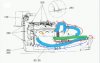
I installed the valves where the manual stated here:

RCGuy was asking where to install the valve on his 215hp SC Challenger 180 in another thread. I started to search to see what I could find to help him out, then I came across this thread http://www.seadooforum.com/showthread.php?78885-Pinch-off-hose-for-towing-in-water where the OP was looking to install the valve exactly where I placed mine (and where the manual seems to reference as well).
The 3rd post says this is not the correct spot for the valve.
Now I am completely confused. Is my valve installed correctly or do I need to move it to the thicker hose that goes to the front underside of the exhaust manifold? Here's where they are currently installed:

I'd just like to confirm the proper valve placement.
I installed the valves where the manual stated here:
RCGuy was asking where to install the valve on his 215hp SC Challenger 180 in another thread. I started to search to see what I could find to help him out, then I came across this thread http://www.seadooforum.com/showthread.php?78885-Pinch-off-hose-for-towing-in-water where the OP was looking to install the valve exactly where I placed mine (and where the manual seems to reference as well).
The 3rd post says this is not the correct spot for the valve.
Now I am completely confused. Is my valve installed correctly or do I need to move it to the thicker hose that goes to the front underside of the exhaust manifold? Here's where they are currently installed:
I'd just like to confirm the proper valve placement.