


This is the installation I promised to post about the Hawk Eye Depth Finder.
The dimensions of the unit are 2” diameter and 1.75” deep. It uses a polarized Liquid Crystal. It comes with a white or black face plate and ring that are interchangeable. The preferred method to install is in dash or a special mounting unit for above dash is available. The Hawk Eye also comes with a cover to protect the face of the gauge. This unit will read from 1.0 to 200 ft deep. It has an alarm that you can set for the upper depth or the lower depth you desire. You can shut it off quickly when it sounds, by pressing the buttons on the face. The alarm signals are audible, red LED or blinking LCD icons. The transducer is included also that can be mounted on the transom or it can be glued inside the Hull of the boat. The transducer has 30 ft. of cable. It has a frequency of 200 KHZ
The unit is a simple 3 wire install. Install time approximate 1.5 hrs not counting cure time of epoxy//needs 12 hrs fully cure.
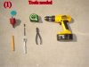
Here is the list of tools you will need to perform the install.
1) Tape measure
2) Power Drill gun
3) 2” hole saw drill (red in picture)
4) Pencil or marker
5) 5.5 mm socket w ¼ ratchet and extension
6) Pair of cutting pliers
7) 4 plastic ties
8) Wire connectors for power and ground connectors
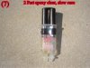
9) 2 part clear epoxy, slow cure (pic7)
10) Piece of 80 grit sand paper//no picture
This install is on my 1997 Challenger Model 5603
I have enclosed pictures of the tools required. (Pic#1) Notice in the picture the green disc. This is what I drilled out of the dash to fit the depth finder in.
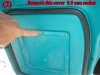
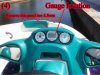
First consider where you want to mount the depth finder. Use the tape measure to measure the open area. I used the ring for the face of the depth finder to determine the exact location, measured it with the tape measure and mark the center of the position to drill the hole with the pencil or marker. I opened the console and unscrewed the bottom cover (5.5mmSocket) (Pic#2) Check for any wires or obstructions. The area was clear and I could route the power and ground with other wires from Tach. and Speedo. I also checked for open room for transducer plug end which there was plenty. (Pic#3) I wanted to mount between the 2 other gauges. I ran the transducer plug end from the Hull of the boat along side the steering cables and control cables up to the front storage compartment with out any problems. Remove the storage box for install. Use stiff piece of wire like a coat hanger if you need to help run the transducer plug end. Sorry no picture. Remove the top cover over gauges shown in (Pic 4) to allow room to drill hole for gauge. Use 5.5mm socket again from access from the cover in (pic2) Now use 2” hole saw and cut out the hole in the plastic be careful and go slowly, as it is very thin. Install the face plate color you want.
Assemble gauge in hole, tighten the supplied bracket on back and pull wires through the grommet in bottom of cover. (Pic 3) Leave the fuse assy. for gauge in top section of cover. Cut the rubber grommet with the cutting pliers and run the transducer wire to the gauge through the 2 holes and plug into the gauge.(Pic3)
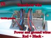
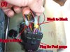
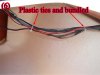
Run the Black and Red wire from the gauge with other wires and connect to a power source that is active when the motor has ignition.(Pic5) If you run it to say the blower it will be active all the time and run the battery down. I chose the power and ground of the fuel gauge as it has enough amps to run the depth gauge and it was in the area. Use the plastic ties to keep bundled up and orderly.(Pic 6) re-assemble all panels, install storage box.
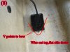
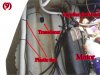
Ok almost done now, I have the location of the transducer already set so look at the pictures and mount it to the hull and your done. Here is how; scuff the fiberglass with 80 grit sand paper to make the surface the size of the transducer smooth. Mix the 2 part epoxy following the directions on package.(Pic7) Surface must be dry and clean. Mix it on cardboard or similar. You’ll need enough to cover both surfaces. Again be sure to follow directions for cure times. Have the wire out the top flat side down with point of transducer facing the front of the boat.(Pic8+9) Stick it down with a twisting motion to remove bubbles and let dry. If the transducer doesn’t stay put use duct tape to help secure it. Now it’s all done look at the job and enjoy.
Finished project (Pic 10)
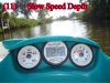
Boat slow speed (Pic 11)
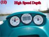
Boat at speed (Pic 12)
The dimensions of the unit are 2” diameter and 1.75” deep. It uses a polarized Liquid Crystal. It comes with a white or black face plate and ring that are interchangeable. The preferred method to install is in dash or a special mounting unit for above dash is available. The Hawk Eye also comes with a cover to protect the face of the gauge. This unit will read from 1.0 to 200 ft deep. It has an alarm that you can set for the upper depth or the lower depth you desire. You can shut it off quickly when it sounds, by pressing the buttons on the face. The alarm signals are audible, red LED or blinking LCD icons. The transducer is included also that can be mounted on the transom or it can be glued inside the Hull of the boat. The transducer has 30 ft. of cable. It has a frequency of 200 KHZ
The unit is a simple 3 wire install. Install time approximate 1.5 hrs not counting cure time of epoxy//needs 12 hrs fully cure.
Here is the list of tools you will need to perform the install.
1) Tape measure
2) Power Drill gun
3) 2” hole saw drill (red in picture)
4) Pencil or marker
5) 5.5 mm socket w ¼ ratchet and extension
6) Pair of cutting pliers
7) 4 plastic ties
8) Wire connectors for power and ground connectors
9) 2 part clear epoxy, slow cure (pic7)
10) Piece of 80 grit sand paper//no picture
This install is on my 1997 Challenger Model 5603
I have enclosed pictures of the tools required. (Pic#1) Notice in the picture the green disc. This is what I drilled out of the dash to fit the depth finder in.
First consider where you want to mount the depth finder. Use the tape measure to measure the open area. I used the ring for the face of the depth finder to determine the exact location, measured it with the tape measure and mark the center of the position to drill the hole with the pencil or marker. I opened the console and unscrewed the bottom cover (5.5mmSocket) (Pic#2) Check for any wires or obstructions. The area was clear and I could route the power and ground with other wires from Tach. and Speedo. I also checked for open room for transducer plug end which there was plenty. (Pic#3) I wanted to mount between the 2 other gauges. I ran the transducer plug end from the Hull of the boat along side the steering cables and control cables up to the front storage compartment with out any problems. Remove the storage box for install. Use stiff piece of wire like a coat hanger if you need to help run the transducer plug end. Sorry no picture. Remove the top cover over gauges shown in (Pic 4) to allow room to drill hole for gauge. Use 5.5mm socket again from access from the cover in (pic2) Now use 2” hole saw and cut out the hole in the plastic be careful and go slowly, as it is very thin. Install the face plate color you want.
Assemble gauge in hole, tighten the supplied bracket on back and pull wires through the grommet in bottom of cover. (Pic 3) Leave the fuse assy. for gauge in top section of cover. Cut the rubber grommet with the cutting pliers and run the transducer wire to the gauge through the 2 holes and plug into the gauge.(Pic3)
Run the Black and Red wire from the gauge with other wires and connect to a power source that is active when the motor has ignition.(Pic5) If you run it to say the blower it will be active all the time and run the battery down. I chose the power and ground of the fuel gauge as it has enough amps to run the depth gauge and it was in the area. Use the plastic ties to keep bundled up and orderly.(Pic 6) re-assemble all panels, install storage box.
Ok almost done now, I have the location of the transducer already set so look at the pictures and mount it to the hull and your done. Here is how; scuff the fiberglass with 80 grit sand paper to make the surface the size of the transducer smooth. Mix the 2 part epoxy following the directions on package.(Pic7) Surface must be dry and clean. Mix it on cardboard or similar. You’ll need enough to cover both surfaces. Again be sure to follow directions for cure times. Have the wire out the top flat side down with point of transducer facing the front of the boat.(Pic8+9) Stick it down with a twisting motion to remove bubbles and let dry. If the transducer doesn’t stay put use duct tape to help secure it. Now it’s all done look at the job and enjoy.
Finished project (Pic 10)
Boat slow speed (Pic 11)
Boat at speed (Pic 12)
Attachments
Last edited by a moderator:
")