Has anyone got any idea how the speedo/sensors work??

Note: This site contains eBay affiliate links for which SeaDooForum.com may be compensated
Status
Not open for further replies.

Minnetonka4me

Premium Member
Premium Member
Me and LouDoo are working on installing a speedo gauge in his 96 GSX. We are having a heck of a time getting it working.

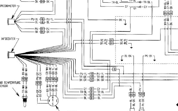
The big gauges only have a single wire for input, power and ground. Small gauges have all three wires coming up to the gauge.

THEN...looking at the 97xp, the sender only has 2 wires...one of which heads to the speedo but not before it goes through the MPEM.

I tried many combos to make the 2 wire work with the small gauge, but it doesnt read.

I am pretty sure the 3 wire senders are all the same, so I assume the MPEMs are doing some sort of conversion.

Anyways I'm thoroughly confused...anyone really looked into this?

Hey lou...did you look to see if its seeing speed on the info gauge? There is a 3 wire plug there...
 
Last edited by a moderator:
Nick, My 96GSX doesn't have a separate speedometer, I plugged the sensor directly into the info. center, this may be the problem, I'm thinking I might need to replace the Tach. with the speedo gauge. I did check my 96GTI it has a three wire sensor but has a separate speedo. The 97GSX has a speedo instead of a tach, you read the rpm's on the info. gauge. The 96 also reads rpm's on the info. gauge.

When I plug the speedo sensor directly into the info. center, it thinks it's seeing the water temp. sensor. BTW the info. center thinks the lake temp. is a constant 79 we can only wish. Also checking the schematic for a 96GSX it is showing the three wire connector for a speedo on the info. gauge.

Are you thoroughly confused?

Lou
 
Hi Nick,

I've been comparing the schematics for a 96GSX which doesn't have a separate speedo to a 97GSX which does. The 97GSX does have a 3 wire connector on the speedo, so I'm thinking I need the separate speedo to replace the tach. I should still be able to get RPM's from the info. center.

Also on the 96 there is an option for a lake temp sensor, which is on the speedo pickup, so this makes sense also. The 97 doesn't have this option.

Lou
 
The 97 is easy it has 2 wires one ground the other like u said goes through the mpem n out cable I think 2, pin 1 .. the three wire speedosensor has one for temp that u can just cut off.
 
The 97 is easy it has 2 wires one ground the other like u said goes through the mpem n out cable I think 2, pin 1 .. the three wire speedosensor has one for temp that u can just cut off.

Well I guess we've hit a wall here, the 96GSX goes from the pickup directly to the info. gauge, and doesn't go through the MPEM, that's the difference.

Just for my information, there are three wires from the speedo pickup, black (assuming this is ground), red, and yellow/black.
Do you know which is speedo signal and temp. sensor?

Lou
 
Last edited by a moderator:
Shouldn't matter I think it just goes through the mpem and connects to a fuse. U can go directly to the gauge . Hook the gauge to power plug and u should see voltage on the single plug. Then flicker it to ground n u will see the gauge mph flicker and that's how u know it works. After connect it to the sensor and while spning the wheel it should more the mph . Otherwise your sensor us no good
 
I'm using the input to the info. center, digital. I'm thinking if I had the stock 97 speedo gauge it would work.

Lou
 
Oh I see, well the signal on a 97 is digital so i don't see why it wouldn't work. The stupid sensor is just open/close while the wheel spins
 
I am pretty sure I sent him a speedo out of a 96 GTX....Which just has an extra wire for the temp sensor. It is a digital gauge though...only one wire for sender, then a power and ground...and a tan for the temp.

The 97 GSX guage doesnt have the temp light...otherwise its the same.

The wire diagram for the GTX just shows the purp/yel just pigtailing off the wire directly. Thats what has me so confused...it should WORK!

In this shot the 3 wires on the bottom right are the sender.

 
Are u going through the mpem I noticed on the seadoo schematic on the 97 xp its label incorrectly maybe on 96 as well . I know the purple wire is the speedometer. Should be pin 1 on the amp connector
 
The schematic I've been using is different, I downloaded it from the manual section of this forum. Here's the one I've been using.

Lou
 

Attachments

  • 96GSXWiring.jpg
    96GSXWiring.jpg
    677.1 KB · Views: 83
So it has two speedometers on that ski? Oh either way that wire connects to both gauges u can see in the drawing. U can tie both gauges together its the same signal wire then it feeds to the speed sensor
 
I don't have the big speedo, that wiring diagram is for a 97, my 96 has 2 tachs., both tachs. work. The schematic Nick has shows a 2 wire connection the one I'm using shows a 3 wire connection.

Lou
 
Nick, Did you get my last PM.
Sorry but I didn't know both of you were out of town for a few days.
Let me know the cost.
 
I took a look at my 96GTI, looks like the same unit, it's too late tonight, but tomorrow I'll switch them out and let y'all know what happens.

Thanks for the help.

Lou
 
I don't have the big speedo, that wiring diagram is for a 97, my 96 has 2 tachs., both tachs. work. The schematic Nick has shows a 2 wire connection the one I'm using shows a 3 wire connection.

Lou

If you look at yours...blk is ground and purp is power. Power goes in and back out...that only leaves one wire for the speedo. The purp/yel


Nick, Did you get my last PM.
Sorry but I didn't know both of you were out of town for a few days.
Let me know the cost.

Ill reply right now.
 
O.K., out of the speed sensor you have black, red, yel/blk. Yel/blk matches up to pu/yl, blk to blk(gnd), and red is either not used or is the temp. sensor. On the info. gauge there is also a single connector blk/red that on the 96GSX is shown as speed sensor reference, currently it's not connected, any ideas?

Lou
 
Yes, I know how the speedos work and can rebuild them. The electronic components are not that expensive but getting the epoxy potted material out without damaging things is difficult, similar to the VTS modules and MPEMs.

The SeaDoo three wire speed sensors are not all the same. Up until 96 or so(there is overlap depending on models), they used a 3 wire that had a signal wire, an open collector, and a ground, usually the wire colors were black, yellow, brown or black, blue/red, purple(from what I remember). When they introduced the lake water temp feature in 96 on the GTX, they redesigned the speed sensor with a 3 wire system with colors black, purple/yellow, and tan/orange where the tan wire is the lake water temp reading which is a simple varying ohm measurement. The black is ground and the purple/yellow is the signal wire but the internal components are different than the previous years and are not interchangeable.

The sensors go bad because the potted epoxy leaks water/moisture around it and kills the electronics. I have repaired seadoo speed sensors but is not worth the time involved. The sensor is actually pretty complicated and is a Magneto-Resistive speed sensor that uses the Hall effect without switching to ground to change voltage when a magnet passes through its field. The 4 lobes of the paddle wheel are actually magnets that change the voltage output with each quarter turn. The rate of this is what determines the speed. Crankshaft and camshaft sensors work the same way using a lobe off the steel crank or cam gear.

The wheels don't go bad, they're just magnets, but they do break lobes off. If your gauge doesn't have moisture in it, most likely it's the speed sensor, they fail frequently.

So, it sounds to me like you have two different speed sensors and they are not interchangeable. Sorry for the long post and I'll get off my soapbox now but I thought this info might be useful to some people.
 
So some speedometers work off a pulse signal and others from voltage variation? Can the speed sensor with the blue wire be connected to the purple yellow and the black and purple be connected to 12v , ground?
 
No, they all work off voltage that varies but that is considered the "pulse" which is the rate that it alternates between two voltages. The newer style will vary between 8.5V and 5.5V with every 1/8 turn. The older style varies between two different voltage readings, can't remember what they were but I do remember the test to check the older style was a resistance check between the black, red, and yellow wires but there are diodes in the sensors so when you test resistance one direction it will be an open circuit and reverse the leads and it will be like 3M ohms resistance. To test the newer style, you check the voltage while it is still connected and slowly turn the paddle wheel and you'll see the voltage alternate.

No, the speed sensor with the blue wire is the older style and will not interchange with the newer purple/yellow wire on the newer speed sensors. I've tried it before just to see what happens and it appears to work for short times but will also act erratically and jump all over the place.
 
Last edited by a moderator:
Status
Not open for further replies.
Back
Top