96 XP Testing the CDI Module

Note: This site contains eBay affiliate links for which SeaDooForum.com may be compensated
Status
Not open for further replies.

JustSteve

New Member
I am not getting spark signal to the coil. Checked the inductive pickup, grounds, plug wire, new coil, ohmed out white wire from mag connector and connector in relay box. Tested the CDI with multimeter and found Black (+) to GY/WH (-) 500K ohms vice 33K ohms specified in the shop manual. Picked up a replacement CDI which measured the same (500K). Still no spark. Does this mean that the new (used) unit is a dud? Manual says that this wire is RPM data to the MPEM.

Thanks.
 
As far as verifying the grounds, did you verify that the little ground strap from the battery to the rear ebox to the coil inside the rear ebox is good. The little pin can corrode in the connector. It terminates at the bottom of the coil and if it doesn't have a good connection you get no spark but the rest of the ski will function.


462.jpg
 
Yep close to 0 ohms from the post to the cylinder heads. From what I read here and in the service manual I need to check coil primary, coil wires, plug boots, test each of these to ground, flywheel pickup coil, wiring from coil to CDI/MPEM, wiring from CDI to coil, connector at the coil box, ground wire from coil box, all fuses, DESS post. May be missing something but I arrived at the CDI after a lot of tinkering. Hate to admit it, but I enjoyed learning about the circuit.

Then I pulled the CDI and found only that one reading off spec. Others were like 10% off, but this pin is significantly different from the spec. And I now have two CDIs with exactly the same discrepancy.

Is this what a bad CDI looks like? I am willing to try another CDI.

BTW RacerXXX I really enjoyed the resto thread on your 96 XP. This one I am trying to get running will be my second, after selling another a decade ago and missing ever since. Now the wiring is 10 years older and I had electrical problems back then.
 
Last edited by a moderator:
Ok, the battery post to engine is just ONE of the grounds. The coil grabs it's ground from the battery via a small wire with a ring terminal on it. That wire goes thru the top of the rear ebox and joins the rest of the grounds in the first pic I posted at the bottom of the coil. If that ring terminal does not have continuity from the battery ground to the coil you will have ZERO spark. Now, in the middle of that is a connector that plugs into the top of the rear ebox, if that ground pin corrodes you get no ground. So, pull the coil portion of the rear ebox, make sure the ring terminal is hooked up to te battery ground and take one meter probe to the battery ground and the other to the spot on the coil inside the box where all the other grounds go. It should go to almost 0.00VDC

I've seen a few eboxes that the ring terminal is crimped on teh insulation and the wire is broken, some that are missing the wire until you pull the connector boot back etc....

Glad you like that thread on the 96, I missed mine when I sold it, now I have them hiding all over.


You can see the ring terminal to the right of the ebox. Under that round rubber boot is the connector I was referencing, pull it and see if there is anything green in there on the pins.


16.jpg
 
I appreciate the detailed guidance. The ground wire is good. 0 ohms from the gang ground screw to the negative terminal on the battery. And that entire contraption is 0 ohms to the engine block.

The white wire to the connector under that boot that you pointed out was suspect. Looked like somebody had jammed a multimeter probe through the insulation, tearing up the conductor. So I cut that wire, stripped it back, and soldered it to the pin. Seems to have good connectivity but I don't think that it's actually getting signal from the CDI. I don't know how to test that for sure. Can I throw a meter on the white wire and read ac voltage during cranking? Unfortunately I no longer have an o-scope to watch for a pulse.

There is one pin in that connector that looks crusty. It's on the red wire. I cleaned it with a brush and contact cleaner but the end of the female pin appears to be physically damaged - a few thousandths short and the end has a 30 degree taper. If I had to guess I would speculate that it had experienced some kind of an arc or spark. It was corroded too. Checked good with a meter after I cleaned it up and smashed it down a bit, but not looking very solid.

I ordered and received a new connector with solder-on pins. I don't own that fancy crimper and I don't think that I like the idea of crimped pins in a salt air environment. And 12 solder joints are 12 chances for a (new) bad connection. What do you think? Replace the connector? Could the red wire cause no spark?
 
Last edited by a moderator:
Without seeing it it's hard to speculate. But, run your coil thru the test on it, in the manual. I'd find it hard to believe that you'd have 2 bad CDI's. I don't have a schematic in front of me right now.
 
Thank you. It's a new coil. Both the primary and secondary check good with a multimeter, including an end-to-end test with the boots on (corrected for resistance of the boots) and a coil to ground test. When I turn the motor over I don't see spark at the plug (one installed, the other held in contact with the unpainted area of the head at the spark plug hole). Gas and compression are there. No spark though.

I agree that two bad CDIs would be strange. That's why I'm interested in whether the resistance values in the shop manual mean anything. I am getting 500K ohms on a wire that should be reading 30K. But it's not even the white wire that carries spark to the coil. If I had a third CDI I would test it with the same meter before installing it and after attempting to start. Maybe this thing eats CDIs for breakfast. Like square black plastic breakfast cereal except no sugar and more expensive.
 
Sounds like the MPEM might have failed. I have seen them perform all their other functions but not let spark through.
 
Thanks Matt for responding.

So the MPEM controls the spark also? Is this done through the control circuit inside the CDI? I can see in the circuit diagram where the signal travels from the exciter coil to the CDI and then on to the coil. It makes sense that the MPEM would have some kind of control as well, such as RPM limiting. There should be a wire that I can test to see if that function is kicking in between the two boxes. Or maybe I should just give up and buy an MPEM.

At this point I really want to figure out if the CDI is good. Does anybody know about whether the ohm test is valid? According to the manual I have two CDIs out of spec.
 
Any chance somebody has a good CDI for a 787 sitting around and would be willing to ohm out the Black (+) to Gray/White (-) wire and tell me what you get? You would be my hero.
 
Im going through something similar with my 96' xp on a hot start issue. check out my most recent thread.

As for CDI, I just swapped mine out. Can you take a picture of the wires you need ohmed? I have one I can test tonight with my DVOM.


Rob


Any chance somebody has a good CDI for a 787 sitting around and would be willing to ohm out the Black (+) to Gray/White (-) wire and tell me what you get? You would be my hero.
 
I'm away from the unit right now but it's easy to describe. On the connector that has three wires, place the negative lead on Gray/White and the positive lead on black. I owe you!

BTW, I did check out your XP thread. Looks like you have your own challenges.
 
Last edited by a moderator:
No worries. Thanks for taking the time to dig through your parts for me.

Anybody else have a CDI for a 96 XP that they would be willing to ohm out for me? I have two suspect units and I'm trying to confirm a problem before I drop $$ on another.
 
Just checked. On those wires it will give you a certain value and then keep climbing.

I'm checking another known good one.
 
Stephen, I see what you mean. The spec is 33K ohms and it's climbing toward 1M ohms. If yours does the same then I'm probably good. Time to look elsewhere.
 
Yeah 3 of them that I tested did the same thing.

What originally happened?

If your getting a good reading from the pickup are you sure the bracket isn't broken or bent ?

Try measuring for AC voltage from the pickup while cranking. See if it gives anything.

Do you have a tachometer? Does it rise slightly while cranking?
If yes, the pickup is good. RPM data is going through the CDI and then through the mpem's rev limiter and kill circuit and is making it out to the tach.
If no, Look towards the pickup and mpem.

Best thing is to use a scope on the output of the pickup to see that there is a pulse coming out of it. AC voltage is another way of telling you that there is a pulse because its giving you a reading of lets say 3 Vac that mean's the pickup is sensing something that is turning on and off and generating a little bit of voltage. The fact that its AC means that.
If there pickup bracket was broken it wouldn't be close enough to the flywheel to pick anything up and you wouldn't get any voltage because it wouldn't be switching on and off and wouldn't be generating a little bit of voltage.

IF your meter reads FREQ or frequency that would be best because it would tell you for sure that the pickup is working and it would tell you something close to the actual rpm of the motor.

If the pickup is good and your sure the wiring is good. we can check the coil and output to the coil.

That coil is almost a dead short on the input side. SO if you measure for voltage there while its connected you won't get hardly anything that you could measure.
But with the coil unplugged you can see an AC signal wihle cranking. It won't be high voltage either.

Another interesting thing.
The wires can come out of the coils and they do corrode inside the coils.
The spark DOES NOT jump to ground like an automotive system. I mean any high enough voltage will jump to the biggest conductor and the engine is one of those things but by design the spark jumps between the plug wires. Its only using the engine block as a path to connect the two spark plugs.

Another interesting thing about our ignition systems.
The 3 piece system with seperate relay and CDI module takes MORE POWER muhahahaha, than the later models (97GTX for example will happily spark at 10.2 volts)
However with ours if you drop below 11.32V while cranking, the CDI will not send a spark signal.

Also if your seeing 11V at the battery, chances are the cdi is seeing almost 9V once all the wiring adds some resistance.
 
Last edited by a moderator:
I'm wondering if your battery just doesn't have enough power once its cranking and your really just dealing with the same quirk as we've all been dealing with.

Something to try...

Connect another jumper from the base of the coil where all the other grounds are to the negative of the battery or the engine.

That engine will crank all day with that ground on the coil missing but won't fire.
 
Still on the road but I should have a spankin new set of custom battery cables to try when I get home Tuesday. Will let you know how it goes.
 
Finally got back home after being away most of the Summer.

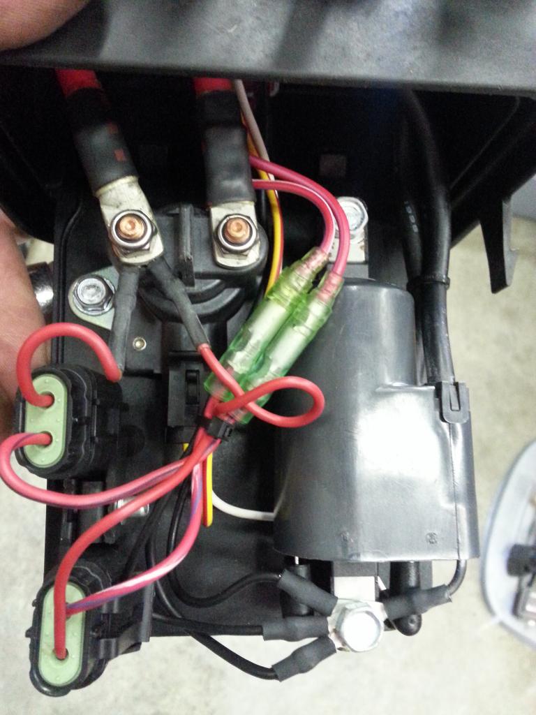
I took your advice and concentrated on the wiring. Replaced the main ground, both large red cables. Then I pulled out the cable connector from the top of the ignition relay box and disassembled it. The crimp on the small black wire that goes to the battery was bright green. The white wire (the one that carries the trigger signal from the pickup above the stator) was also extremely corroded.

So I cut the wires from all six pins and began stripping them back until I got to shiny copper strands. The black wire was oxidized black under the insulation so I replaced the entire wire. The white wire wasn't as simple because it runs all the way forward to the CDI module. That particular wire was oxidized back at least a foot so I replaced it as well.

Six new female pins, a new female connector housing, two battery cables, a starter cable for a grand total of around $20US. Beep, beep...then vroom!

Thanks for the advice and for keeping me on task to track this problem down.

As a side note, I met a gentleman while I was away in the Atlanta area who hooked me up with some plastic parts for my XP. He told me that, in the 20 years he has worked on these machines, 90% of the problems have turned out to be electrical and most of them could be fixed by cleaning corrosion off the connector pins.

Sounds plausible.

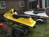
Here's a shot of the new (to me) XP ready to go back into the water. Gotta make the best of what's left of Summer.

YellowXP.jpg
 
All worked out fine. No cutouts on the test flight. This baby moves out!

Thanks again for the help.
 

Attachments

  • IMG_6675.jpg
    IMG_6675.jpg
    2.1 MB · Views: 33
Status
Not open for further replies.
Back
Top