No spark
Member
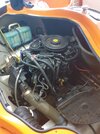
Hi all, I went to start my Seadoo 240 efi v6 and it wouldn’t start so I checked if there was spark : There is No spark on any of the 6 cdi coils. So I checked the cut off lanyard
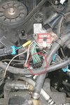
The black and yellow wire and followed it all the way back to the ecm disconnected it and checked it for ground :No ground (until I pull the lanyard out) so I think it’s all good that side of the ecm?
Then I went to the black and green wire wire coming from ecm to cdi unit’s I understand that this goes to the pin B of all cdi units ? When I check this for ground :YES it is grounded . I’m now not sure what to check now. Help would be much appreciated.